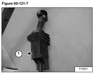
Lift the boot cover (Item 1) [Figure 60-121-7].
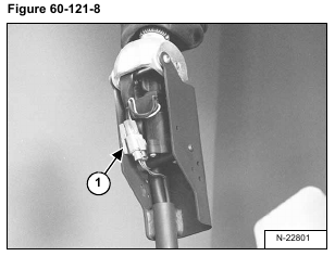
Disconnect the harness connector (Item 1) [Figure 60-121-8] from the handle sensor connector.
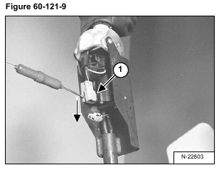
Remove the handle sensor connector (Item 1) [Figure 60-121-9] from the clip.
NOTE: Pry out with a small screw driver and push the connector down.
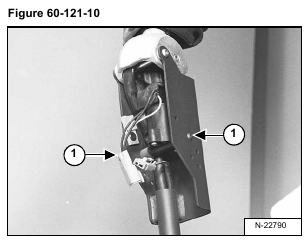
Use an allen wrench, remove one of the two mounting screws (Item 1) [Figure 60-121-10] from the handle sensor.
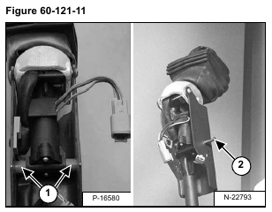
Remove the two plastic spacers (Item 1) and the metal spacer (Item 2) [Figure 60-121-11] from the handle sensor.
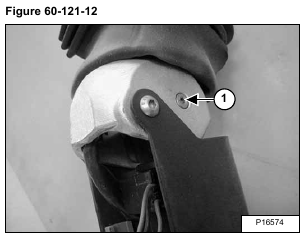
Remove the top mounting bolt (Item 1) [Figure 60-121-12] from the handle sensor.
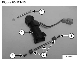
Remove the handle sensor (Item 1) [Figure 60-121-13] from the handle assembly.
NOTE: The sensor (Item 1) [Figure 60-121-13] can only be replaced as a complete assembly.
Check the spacers (Item 2) and screws (Item 3) [Figure 60-121-13] and replace as needed.
Installation: When installing the handle sensor into the control handle, check the routing of the switch handle wire harness (Item 1) [Figure 60-121-14] to assure proper return of the control handle to neutral.
