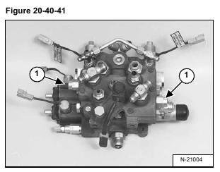
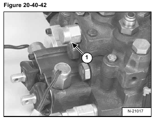
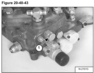
Remove the lock valves (Item 1) [Figure 20-40-41], [Figure 20-40-42] & [Figure 20-40-43] from the BICSTM
valve.
Installation: Tighten the lock valves to 25 ft.-lbs. (34 Nm) torque.
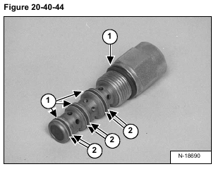
Remove the O-rings (Item 1) and back-up rings (Item 2) [Figure 20-40-44] from both the tilt and lift lock valves.
Install new O-rings (Item 1) and back-up rings (Item 2) [Figure 20-40-44] on the tilt and lift lock valves.
Reverse the removal procedure to install the lock valve.


