Install jackstands under the rear corners of the loader.
Raise the lift arms and install an approved lift arm support device. (See Installing Lift Arm Support Device
on Page 10-20-1.)
Raise the operator cab. (See Raising The Operator Cab on Page 10-30-1.)
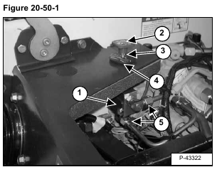
The lift lock by-pass valve (Item 1) [Figure 20-50-1] is located under the right side of the control panel.
Hold the by-pass control knob (Item 2) and loosen the jam nut (Item 3) [Figure 20-50-1] on the by-pass valve
shaft.
Remove the by-pass control knob and jam nut from the valve shaft.
Remove the rubber washer (Item 4) [Figure 20-50-1].
Disconnect the two tubelines (Item 5) [Figure 20-50-1] from the lift lock by-pass valve.
Cap or plug all open hydraulic connections.
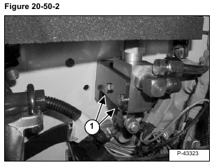
Remove the two mounting bolts (Item 1) [Figure 20-50-2].
Installation: Tighten the mounting bolts to 180-200 in.-lbs. (21-23 Nm) torque.
Remove the lift arm by-pass valve.

