The tools listed will be needed to do the following procedure:
MEL10003 – Hydraulic Tester
MEL10006 – Hydraulic Test Kit
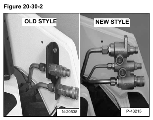
NOTE: The procedure listed below should be used for all loaders (With either the new or old style
front hydraulic couplers) [Figure 20-30-2].
Loaders S/N 515842310 and Above, with the new front hydraulic couplers, release the auxiliary pressure when the coupler is pushed in. This can be done manually, or automatically when the operator pushes the hose on to the coupler to make the connection. The engine must be stopped before making this connection.
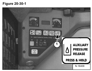
• Press the AUXILIARY PRESSURE RELEASE Button (Item 1) [Figure 20-30-1]. Hold it for two seconds.
The engine will stop and release auxiliary hydraulic pressure on Loaders S/N 515842309 and Below .
• Pressing the AUXILIARY HYDRAULIC RELEASE Button with the instrument panel power on and the engine stopped, will also release hydraulic pressure on Loaders S/N 515842309 and Below.
Lift and block the loader. (See LIFTING AND BLOCKING THE LOADER on Page 10-10-1.)
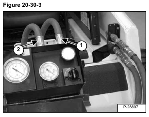
Connect the IN port (Item 1) [Figure 20-30-3] of the hydraulic tester to the bottom (female) quick coupler on
the loader.
Connect the OUT port (Item 2) [Figure 20-30-3] of the hydraulic tester to the top (male) quick coupler on the
loader.
Connect the remote start tool. (See REMOTE START on Page 10-60-1.)
Start the engine with the remote start tool.
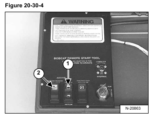
Press the maximum flow/variable flow switch (Item 1) [Figure 20-30-4] twice to activate maximum flow. The
switch will illuminate to indicate the maximum flow rate is active.
The correct pressure for the main relief is 2500-2600 PSI (17237-17926 kPa).
Press the auxiliary pressure release (Item 2) [Figure 20-30-4] and hold the switch for three seconds to release
hydraulic pressure to the front and/or rear auxiliary couplers on Loaders S/N 515842309 & Below. On Loaders S/N 515842310 & Above, push the front hydraulic couplers in to release the pressure before servicing the main relief valve.


