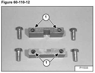
Apply a bead of polyurethane sealer (P/N 6633583) (Item 1) [Figure 60-110-12] around the bolt holes on the blocks.
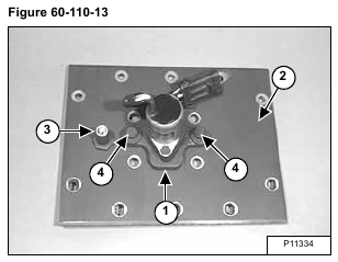
Install the electric solenoid/bracket assembly (Item 1) to the center chaincase cover (Item 2) [Figure 60-110-13].
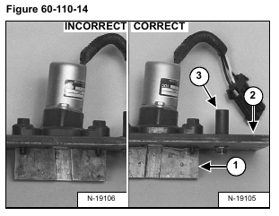
NOTE: Bolt (Item 3) [Figure 60-110-13] & [Figure 60-110-14] represents the rear of the chaincase cover.
Install and tighten the two bolts (Item 4) [Figure 60-110-13].
Install the traction lock guides (Item 1) to the chaincase cover (Item 2) [Figure 60-110-14] using the four bolts (removed earlier).
Do not tighten at this time.
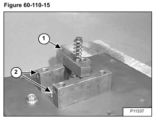
Install the traction wedge assembly (Item 1) into the solenoid and traction lock guides (Item 2) [Figure 60-110-15].
After the bolts have been tightened recheck to make sure the shaft assembly is moving freely in the guides.
Remove the wedge assembly (Item 1) [Figure 60-110-15].
NOTE: The wedge assembly must slide freely in the grooves of the guides. Tighten the four guide bolts to 90-100 ft.-lbs. (123-135 Nm) torque.
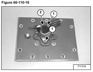
Remove the two bolts (Item 1) and remove the electric solenoid (Item 2) [Figure 60-110-16] from the center chaincase cover.
Install the chaincase cover (Item 1) using the ten mounting bolts (Item 2) [Figure 60-110-17].
Tighten to 25-28 ft.-lbs. (34-38 Nm) torque.
NOTE: Thoroughly clean and dry the bolts and apply LOCTITE #242.
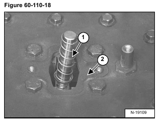
Install the wedge assembly (Item 1) [Figure 60-110-18] into the grooves in the traction lock guides making sure that there is no binding.
Install the gasket (Item 2) [Figure 60-110-18].
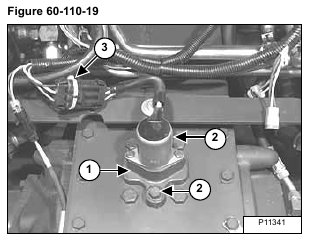
Install the solenoid mounting bracket assembly (Item 1) on the chaincase cover using the two bolts (Item 2) [Figure 60-110-19] and tighten to 25-28 ft.-lbs. (34-38 Nm) torque.
NOTE: Be sure the solenoid mounting bracket is installed in the same position. The solenoid mounting surface has a slight angle which tips the top of the solenoid toward the rear of the loader when installed correctly.
Install a new DO NOT MODIFY sta-strap (Item 3) [Figure 60-110-19] (P/N 6665527) on the electric solenoid connector.
Install the control panel. (See Removal and Installation on Page 50-100-1.)
Install the engine speed control. (See Removal And Installation on Page 70-20-1.)
Lower operator cab. (See Lowering The Operator Cab on Page 10-30-2.)
Perform the BICSTM inspection procedure. (See BICSTM SYSTEM on Page 60-90-1.)
