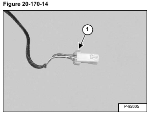
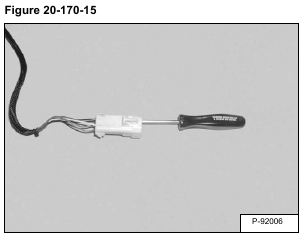
Remove the connector lock (Item 1) [Figure 20-170-15].
Depress the wire terminal tabs and remove the wires from the back of the electrical connector [Figure 20-170-15].
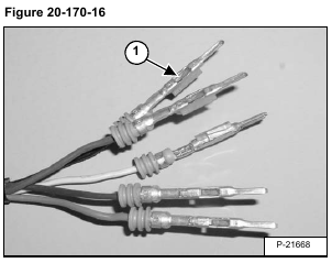
Installation: Re-bed the tab (Item 1) [Figure 20-170-16] on each wire before installing the electrical connector.
Installation: The wires must be installed in the proper locations in the wire connector, listed below.
A Green
B Brown
C Red
D Black
E White
Check each wire to be certain the tab locks into position.
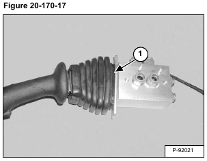
Cut and remove the cable tie (Item 1) [Figure 20-170-17].
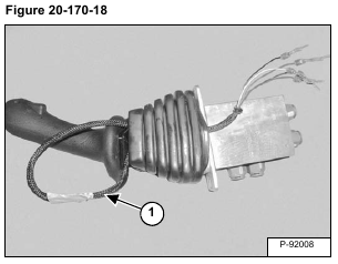
Route the harness (Item 1) [Figure 20-170-18] through the top of the dust boot.
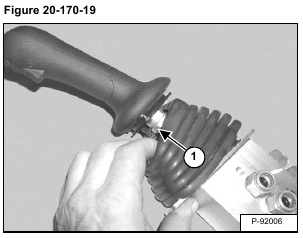
Loosen the nut (Item 1) [Figure 20-170-19] and remove the handle and dust boot.
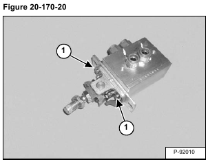
Remove the four bolts (Item 1) [Figure 20-170-20].
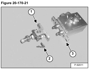
Remove the pivot assembly (Item 1), detent lock (Item 2), and plate (Item 3) [Figure 20-170-21].
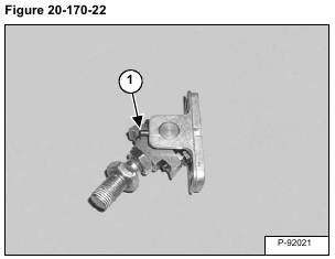
Remove the roll pin (Item 1) [Figure 20-170-22].
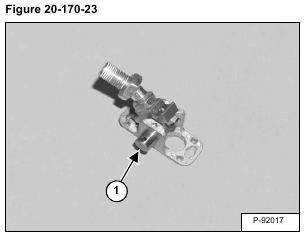
Remove the pivot pin (Item 1) [Figure 20-170-23].
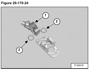
Remove the lever (Item 1). Remove the shim (Item 2) [Figure 20-170-24] from both sides of the lever.
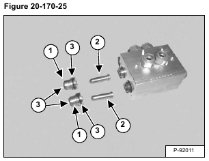
Remove the bushings (Item 1) and push rods (Item 2).
Remove the O-rings (Item 3) [Figure 20-170-25] from the ID and OD of the bushings.
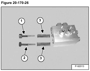
Remove the blade raise spool assembly (Item 1), blade lower / float spool assembly (Item 2) and springs (Item 3) [Figure 20-170-26].
NOTE: The spool assemblies must be installed in the correct bores or the float function of the blade will not work correctly.
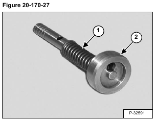
Compress the spring (Item 1) and remove the seat (Item 2) [Figure 20-170-27].
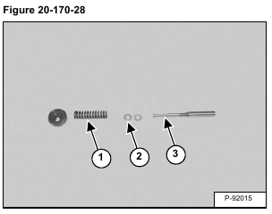
Remove the spring (Item 1) and shims (Item 2) from the spool (Item 3) [Figure 20-170-28].
