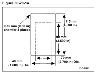
The following tools must be fabricated for this procedure:
1. Driver Tool – see figure [Figure 30-20-14].
2. Support Fixture – Tube, 90 mm ID x 6,35 mm wall x 162,4 mm long (3.0 in ID x 0.250 in wall x 6.0 in long).
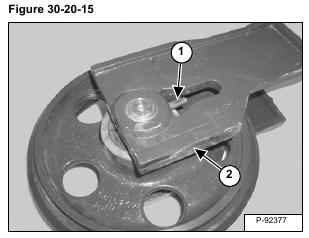
Remove the roll pin (Item 1) and block (Item 2) from both sides of the shaft [Figure 30-20-15].
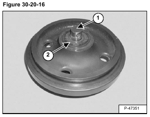
Remove any corrosion or paint from both ends of the exposed shaft (Item 1) [Figure 30-20-16] that could affect seal removal or damage the new seal during installation.
Remove the seal (Item 2) [Figure 30-20-16] from both sides of the idler.
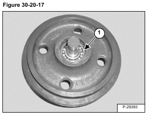
Remove the snap ring (Item 1) [Figure 30-20-17] from both sides of the idler.
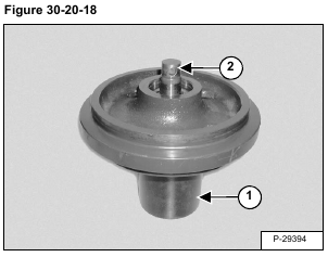
Place the idler on the support fixture (Item 1) [Figure 30-20-18].
Using a soft faced hammer, tap the shaft (Item 1) [Figure 30-20-18] and bearing out the bottom of the idler.
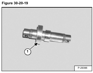
Slide the bearing (Item 1) [Figure 30-20-19] off the shaft.
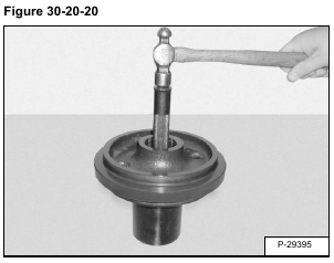
Turn the idler over, and using a bearing driver, remove the second bearing (Item 1) [Figure 30-20-20].
