Raise the lift arms and install an approved lift arm support device. (See Installing on Page 10-20-1.)
Lift and block the loader. (See Procedure on Page 10-10-1.)
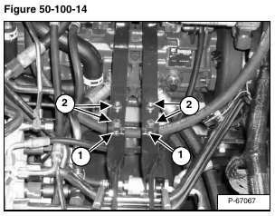
Scribe a mark across the top of the steering linkage bars (Item 1) [Figure 50-100-14] which are connected to the steering shaft on the control panel.
Remove the four steering linkage mounting bolts (Item 2) [Figure 50-100-14].
Installation: Align the marks on the steering linkage bars. Tighten the steering linkage mounting bolts to 35 – 40 ft.-lb. (47,5 – 54,2 N•m) torque.
NOTE: After removal and installation of the linkage, the linkage neutral adjustment procedure must be performed. See Page 50-100-13 for Linkage Neutral Adjusting procedure.
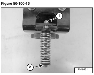
Remove the nut (Item 1) from the end of the centering spring shoulder bolt (Item 2) [Figure 50-100-15].
Remove the bolt/spring assembly.
Installation: Tighten the centering spring bolt and a NEW lock nut to 25 – 28 ft.-lb. (34 – 38 N•m) torque.
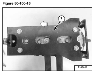
Slide the centering plate (Item 1) [Figure 50-100-16] to the right to remove it from the hydrostatic pumps.
NOTE: Directions are shown and stated as if you were sitting in the operators seat.
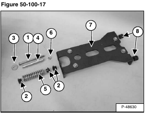
The centering plate/centering spring assembly consists of the following parts [Figure 50-100-17]:
ITEM DESCRIPTION
1. Bolt
2. Bushings
3. Washer
4. Bushing Spacer
5. Spring
6. Lock Nut
7. Centering Plate
8. Guide Bushings
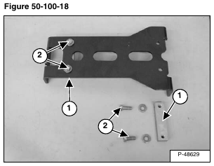
Check the wear on the centering blocks (Item 1) [Figure 50-100-18].
If the centering blocks need replacement, remove the bolts (Item 2) [Figure 50-100-18]. Remove the centering blocks.
Installation: Tighten the centering block bolts to 35 – 40 ft.-lb. (47,5 – 54,2 N•m) torque.
NOTE: The washers go between the bolts and the centering plate.
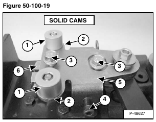
NOTE: If the centering blocks are worn, they can be removed and rotated 180 degrees and reinstalled. If the solid cams are worn, they can be loosened and rotated 90 degrees and reinstalled.
If the surface of any of the four solid pintle cams (Item 1) are worn, loosen the bolt (Item 2) and rotate the cams 1/4 turn [Figure 50-100-19].
Remove the bolts and washers (Item 3) [Figure 50-100-19] from the pintle.
Installation: Tighten the bolts to 35 – 40 ft.-lb. (47,5 – 54,2 N•m) torque.
Loosen the creep adjustment bolt (Item 4) [Figure 50-100-19].
Remove the pintle arm (Item 5) from the pintle base (Item 6) [Figure 50-100-19].
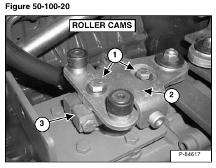
Remove the bolts and washers (Item 1) [Figure 50-100-20] from the pintle.
Installation: Tighten the bolts to 35 – 40 ft.-lb. (47,5 – 54,2 N•m) torque.
Remove the pintle arm (Item 2) from the pintle base (Item 3) [Figure 50-100-20].
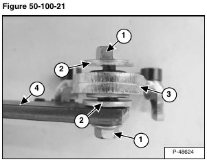
Remove the bolt and nut (Item 1) [Figure 50-100-21].
Inspect the washers (Item 2), pintle arm (Item 3) and the steering linkage bar (Item 4) for damage and replace as needed [Figure 50-100-21].
NOTE: The washers (Item 2) [Figure 50-100-21] are hardened, and should only be replaced through Bobcat Parts.
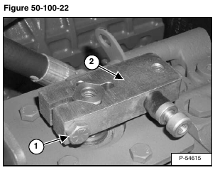
Loosen the bolt (Item 1) and remove the pintle base (Item 2) [Figure 50-100-22].
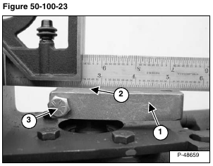
NOTE: When installing the pintle base (Item 1) onto the pump shaft, the cutouts on the pump shaft will not line up with the bolt (Item 3) [Figure 50-100-23].
Installation: Install the pintle base (Item 1) onto the pump shaft (Item 2) [Figure 50-100-23]. The top of the pintle base should be level with the top of the pump shaft.
Tighten the bolt to 35 – 40 ft.-lb. (47,5 – 54,2 N•m) torque.
NOTE: After installing the linkage onto the hydrostatic pumps the linkage neutral adjustment procedure must be performed. See Page 50-100-13 for Linkage Neutral Adjusting procedure.
