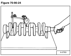
Put the crankshaft on V-blocks. Install a dial indicator on the center journal [Figure 70-90-24].
Turn the crankshaft at a slow rate to obtain the misalignment (one half of the alignment measurement).
If the misalignment exceeds the allowable limit, replace the crankshaft.
Alignment 0.0008 in. (0,02 mm)
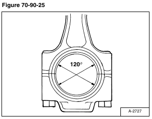
Tighten the connecting rod bolts to 33 – 36 ft.-lb. (45 – 49 N•m) torque.
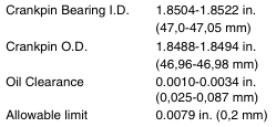
Measure the crankpin bearing I.D. [Figure 70-90-25].
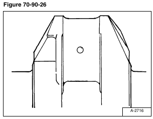
Measure the crankpin O.D. [Figure 70-90-26].
Calculate the oil clearance.
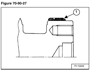
Check the wear on the crankshaft sleeve (Item 1) [Figure 70-90-27].
If the wear exceeds the allowable limit or the seal leaks oil, replace the sleeve.
Wear of Sleeve 0.0039 in. (0,1 mm)
The special tool set will be needed to replace the crankshaft sleeve.
Remove the sleeve.
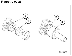
Install the sleeve guide (Item 1) and stop (Item 2) [Figure 70-90-28].
Heat the sleeve to approximately 300° F (150° C). Install the sleeve on the crankshaft using the special driver tool (Item 3) [Figure 70-90-28].
NOTE: The sleeve is installed with the larger chamfered surface to the front of the crankshaft (Item 1) [Figure 70-90-27 on Page 9].
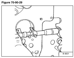
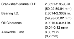
Measure the I.D. of the No. 1 crankshaft bearing [Figure 70-90-29].
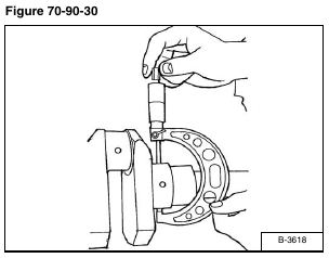
Measure the O.D. of the crankshaft journal [Figure 70-90-30].
Calculate the oil clearance.
If the clearance exceeds the allowable limit, replace the crankshaft bearing.
Bearing 1:
Bearing I.D. 2.3614-2.3637 in. (59,98-60,04 mm)
Journal O.D. 2.3591-2.3598 in. (59,92-59,94 mm)
Oil Clearance 0.016-0.0046 in. (0,040-0,12 mm)
Allowable Limit 0.0079 in. (0,2 mm)
NOTE: Make sure you use the correct size bearing when installing. Oversize bearings are generally marked.
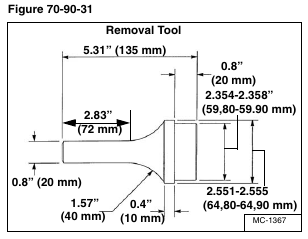
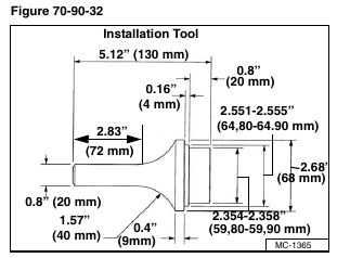
To remove the front bearing make the tool as shown in figure [Figure 70-90-31].
To install the front bearing make the tool as shown in figure [Figure 70-90-32].
Remove the front bearing with the special removal tool [Figure 70-90-31].
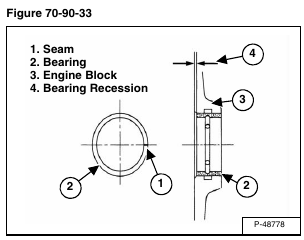
Installation: Clean the new bearing (Item 2) and bore, apply oil to the bearing and bore. Install the new bearing with the seam (Item 1) [Figure 70-90-33] towards the exhaust manifold side, using the installation driver tool.
Check the depth (Item 4) of the bearing (Item 2) from the face of the engine block (Item 3) [Figure 70-90-33]. This will ensure proper bearing alignment with the crankshaft.
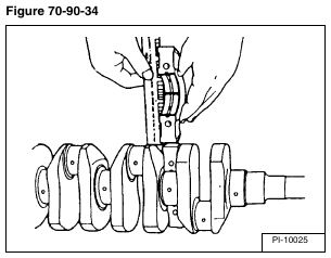
Clean the crankshaft journal and bearing. Put a strip of press gauge on the center journal.
Install the main bearing case halves and tighten the bolts.
Remove the bearing case halves.
NOTE: DO NOT turn the crankshaft with the press gauge installed. Incorrect measurements will be obtained.
Measure the flattened press gauge [Figure 70-90-34].
If the clearance exceeds the allowable limit, replace the No. 2 crankshaft bearing.
