Remove the cylinder head. (See Cylinder Head Removal And Installation on Page 70-80-4.)
Remove the top edge from the cylinder bore with a ridge reamer.
Remove the oil pan.
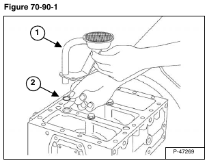
Remove the oil pump strainer (Item 1) and O-ring (Item 2) [Figure 70-90-1] by tapping the edge of the strainer with a soft faced hammer.
Turn the flywheel and put a pair of connecting rods at bottom dead center.
Remove the connecting rod bolts.
Installation: Tighten the connecting rod bolts to 33 – 36 ft.-lb. (44 – 49 N•m) torque.
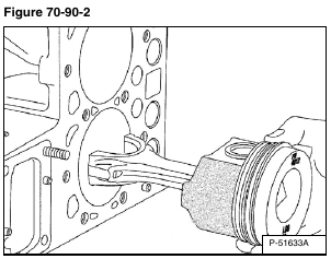
Remove the rod cap and bearing [Figure 70-90-2].
Use a hammer handle and push the piston/connecting rod assembly out of the cylinder bore [Figure 70-90-2].
NOTE: Make sure the pistons are marked so they will be returned to the same cylinder bore.
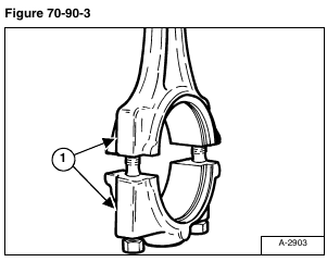
Installation: Make sure the marks on the connecting rod and bearing are aligned when installing the bearing cap (Item 1) [Figure 70-90-3].
Repeat the procedure to remove the other piston/connecting rod assemblies from the engine block.
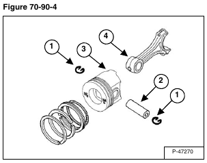
Remove the piston rings [Figure 70-90-4].
Remove the snap ring (Item 1) and piston pin (Item 2) [Figure 70-90-4].
Separate the piston (Item 3) from the connecting rod (Item 4) [Figure 70-90-4].
NOTE: Mark the piston (Item 3) [Figure 70-90-4] and connecting rod (Item 4) [Figure 70-90-4] with the same number to ensure correct installation and proper cylinder placement.
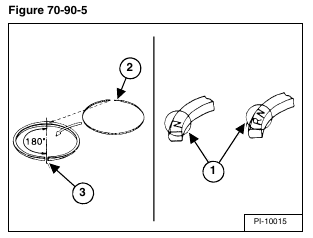
Installation: When installing new rings, assemble the ring so the mark (Item 1) near the gap faces the top of the piston. When installing the oil ring, place the expander joint (Item 2) on the opposite side of the oil ring gap (Item 3) [Figure 70-90-5].
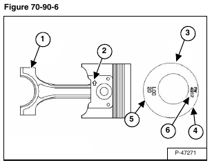
Installation: When reassembling, align the marks (Item 1) on the connecting rod and piston (Item 2). Heat the piston in clean engine oil to 176° F (80° C) and tap the piston pin into position. Place the piston rings so that there are gaps every 120 degrees (Items 3, 4 & 5) [Figure 70-90-6] with no gap facing the piston pin in the cylinder.
NOTE: Assemble the piston to the connecting rod with the FW mark (Item 6) [Figure 70-90-6] is facing the flywheel side and the connecting rod mark (Item 1) [Figure 70-90-6] facing the injection pump side.
