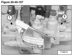
Locate the two BICS lock valves, (Item 1) is for the tilt circuit and (Item 2) [Figure 20-40-107] is for the lift circuit.
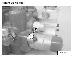
Remove the lift lock valve (Item 1) [Figure 20-40-108] from the back of the control valve.
Installation: Lightly lubricate the lock valve O-rings and tighten to 20 – 24 ft.-lb. (27 – 33 N•m) torque.
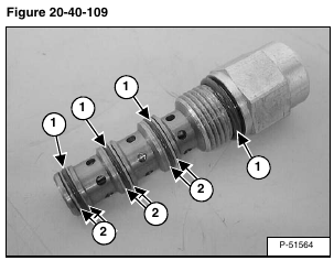
Remove the O-rings (Item 1) and back-up rings (Item 2) [Figure 20-40-109] from the lift lock valve, and replace with new.
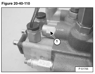
Locate the tilt circuit lock valve (Item 1) [Figure 20-40-110].
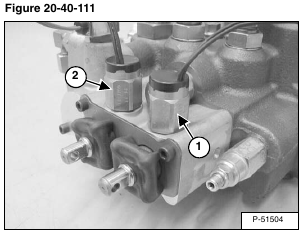
Remove the lift spool lock solenoid (Item 1) [Figure 20-40-111].
Remove the tilt spool lock solenoid (Item 2) [Figure 20-40-111].
Installation: Lubricate the O-rings and tighten the spool lock solenoids to 38 – 45 ft.-lb. (52 – 61 N•m) torque.
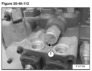
Remove the tilt lock valve (Item 1) [Figure 20-40-112] from the front of the control valve.
Installation: Lightly lubricate the lock valve O-rings and tighten to 20 – 24 ft.-lb. (27 – 33 N•m) torque.
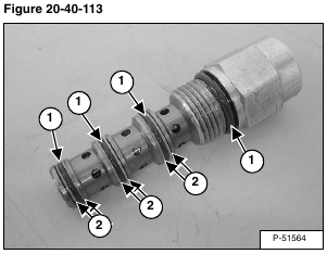
Remove the O-rings (Item 1) and back-up rings (Item 2) [Figure 20-40-113] from the tilt lock valve, and replace with new.
