Lift and block the loader. (See Procedure on Page 10-10-1.)
Raise the lift arms and install an approved lift arm support device. (See Installing on Page 10-20-1.)
Raise the operator cab. (See Raising on Page 10-30-2.)
Clean the area around the control valve.
Drain the hydraulic reservoir.(See Removing And Replacing Hydraulic Fluid on Page 10-120-2.)
Remove the control panel. (See Removal and Installation on Page 50-100-2.)
Remove the right rear tire.
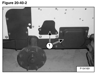
Locate and remove the access covers (Item 1) [Figure 20-40-2] on the right side of the machine.
Mark all tubelines and hoses for correct installation.
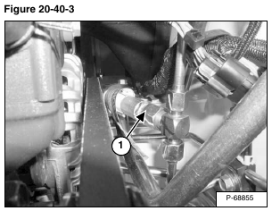
The fixed end main valve hose (Item 1) [Figure 20-40-3] is connected to a fixed end fitting on the control valve.
The hose is routed to the back upright where the hose is connected to a tee fitting that feeds the base end of both lift cylinders. The hose must be removed at the back tee fitting, located in the right side upright.
NOTE: Remember the hose routing for ease of control valve installation.
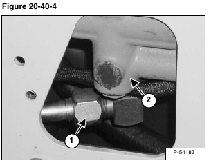
Disconnect the inlet tubeline (Item 1) from the control valve (Item 2) [Figure 20-40-4] through the access opening.
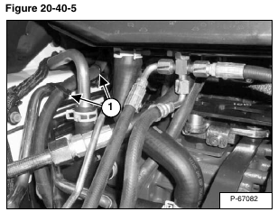
Remove the tie-straps (Item 1) [Figure 20-40-5] from the fixed end main valve hose.
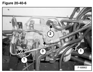
Mark and disconnect the five electric solenoid connectors for correct installation (Item 1) [Figure 20-40-6].
Remove the outlet tubeline (Item 2) [Figure 20-40-6] from the control valve to the hydraulic oil cooler.
Disconnect and cap the drain hose (Item 3) [Figure 20-40-6].
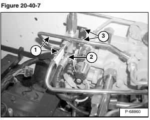
Disconnect and remove the tubelines (Item 1) [Figure 20-40-7] from the lift arm bypass valve to the control valve.
Disconnect and cap the hose (Item 2) [Figure 20-40-7] from the lift arm bypass valve to the drive motor case drain.
Remove the two lift arm bypass valve mounting bolts (Item 3) [Figure 20-40-7] and remove the valve.
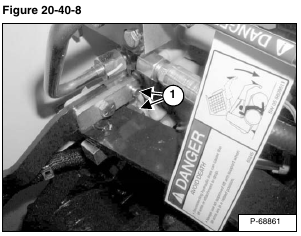
Remove the connector pins (Item 1) [Figure 20-40-8].
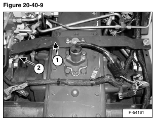
Remove the control pedal cross bar linkage (Item 1) and tilt linkage (Item 2) [Figure 20-40-9].
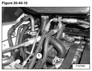
Disconnect and cap the charge pressure tubeline (Item 1) [Figure 20-40-10] from the control valve.
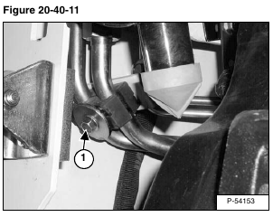
Remove tubeline clamp bolt (Item 1) [Figure 20-40-11] from the auxiliary tubelines in the left rear upright.
Installation: Tighten bolt to 15 – 20 ft.-lb. (20 – 27 N•m) torque.
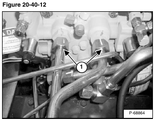
Remove and cap both tubelines (Item 1) [Figure 20-40-12] from the auxiliary section of the control valve.
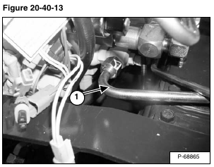
Disconnect and cap the tubeline (Item 3) [Figure 20-40-13] from the lift section of the control valve.
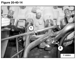
Disconnect and cap the tubelines (Item 1) and (Item 2) [Figure 20-40-14] from the tilt section of the control valve.
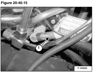
Remove the fixed-end main valve hose (Item 1) [Figure 20-40-15] from the main control valve fitting.
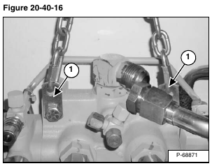
Connect a hoist to the lifting brackets (Item 1) [Figure 20-40-16] on the control valve.
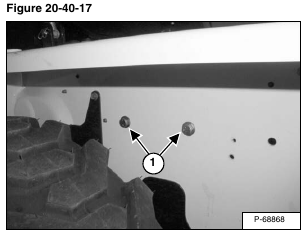
Remove the two mounting bolts (Item 1) [Figure 20-40-17] that secure the control valve to the side of the loader.
Remove the control valve from the loader.
Reverse the removal procedure to install the hydraulic control valve.
