The tools listed will be needed to do the following procedure:
MEL10003 – In-Line Hydraulic Tester
MEL10006 – Flowmeter Fitting Kit
NOTE: When testing the hydraulic flow of a machine, hoses must be at least 3/4 inch in diameter and connected directly to the hydraulic tester without using any type of “quick coupler” on the connection to the tester. Also make sure your hydraulic tester is capable of at least 50 GPM.
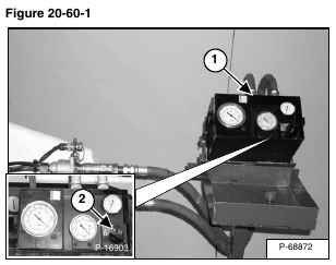
Install a hydraulic tester (Item 1) [Figure 20-60-1] onto the front auxiliary quick couplers.
This procedure will require a operator in the cab and one operator running the tester.
Start the engine and run at low idle RPM. Press the Front Auxiliary button. Engage the front auxiliary with the trigger on the right handle. Make sure the tester is connected correctly. If no flow is indicated on the tester, the hoses are connected wrong. With the hoses connected correctly, increase the engine speed to full RPM*.
Warm the fluid to 140° F (60° C) by turning the restrictor control clockwise on the tester so it reads about a 1000 PSI (69 bar).
NOTE: DO NOT EXCEED 3300 PSI.
Turn the restrictor control (Item 2) [Figure 20-60-1] on the tester counterclockwise to obtain free flow, the flow should be approximately 16 – 17 GPM. Start turning the restrictor clockwise, causing more restriction on the flow.
The GPM should drop off slightly until the pressure reaches approximately 2400 PSI. At approximately 2400 PSI the flow should start decreasing rapidly until the pressure reaches 2650 – 2750 PSI. At 2650 – 2750 PSI the flow should be at 0 GPM. Turn the restrictor (Item 2) [Figure 20-60-1] counterclockwise to free flow. Shut the front auxiliary hydraulics off.
If flow and pressure specs are not obtained, go to Direct Pump Testing. (See Direct Pump Test (Standard Section) on Page 20-60-2.)
*Refer to (See Hydraulic System on Page SPEC-10-3.) for system relief pressure and full RPM.
