Lift and block the rear of the loader. (See Installing on Page 10-20-1.)
Raise the lift arms and install an approved lift arm support device. (See Procedure on Page 10-10-1.)
Raise the operator cab. (See Raising on Page 10-30-2.)
Drain the hydraulic fluid from the reservoir. (See Removing And Replacing Hydraulic Fluid on Page 10-
120-2.)
Open the rear door of the loader.
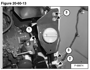
Remove the nut from the speed control linkage (Item 1) [Figure 20-60-13].
Disconnect the rear light electrical connector (Item 2) [Figure 20-60-13].
Remove the fuel fill and belt shield mounting screws (Item 3) [Figure 20-60-13].
Remove the belt shield lower the fuel fill to the bottom of the loader.
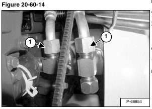
Disconnect and cap the outlet hoses (Item 1) [Figure 20-60-14] from the back of the hydraulic pump.
Remove the Power Bob-Tach block if equipped. (See Removal And Installation on Page 20-130-1.)
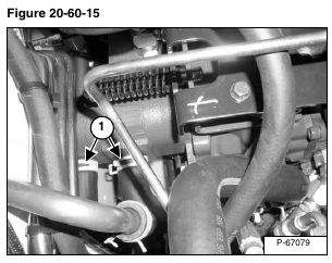
Disconnect and cap the inlet hoses (Item 1) [Figure 20-60-15] from the front of the hydraulic pump.
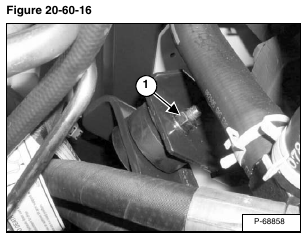
Remove the right front engine mount (Item 1) [Figure 20-60-16].
Installation: Tighten the engine mount bolt to 70 ft.-lb. (95 N•m) torque.
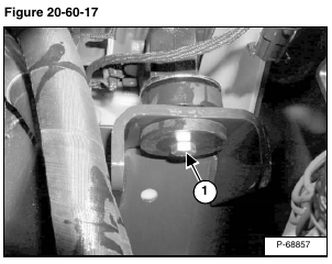
Remove the left front engine mount (Item 1) [Figure 20-60-17].
Installation: Tighten the engine mount bolt to 70 ft.-lb. (95 N•m) torque.
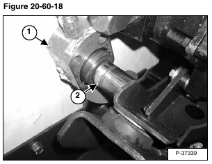
Use a port-a-power (Item 1) [Figure 20-60-18] to push the engine/hydrostatic pump assembly away from the mainframe.
NOTE: A shaft (Item 2) [Figure 20-60-18] with the dimensions of 1.5” diameter by 2.125” long will be needed to push the engine/hydrostatic pump assembly.
NOTE: Push the engine/hydrostatic pump assembly only as far as needed to remove the gear pump.
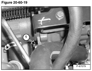
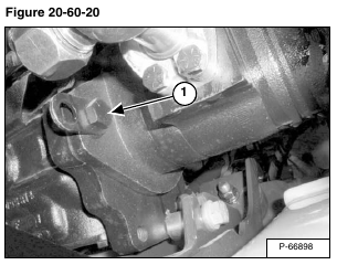
Remove the two mounting bolts (Item 1) [Figure 20-60-19] and [Figure 20-60-20] from the hydraulic pump.
Installation: Tighten the mounting bolts to 55 – 60 ft.-lb. (75 – 85 N•m) torque.
Remove the hydraulic pump from the loader.
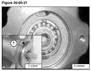
Replace the O-ring (Item 1) [Figure 20-60-21] on the hydraulic pump.
Reverse the removal procedure to install the hydraulic pump.
