The loader’s right hand side hydraulic controller can be removed with the hydrostatic pump still in the loader. The loader’s left hand side hydraulic controller can only be removed when the hydrostatic pump is separated from the engine/hydrostatic pump cast mount.
Controller solenoids can be bled of trapped air in the controller. This should be performed when hydraulic controllers are replaced, removed or uncommanded oscillations in the controls are present.
Raise the lift arms and install and approved lift arm support device. (See Installing on Page 10-20-1.)
Place the loader on jack stands. (See Procedure on Page 10-10-1.)
Raise the operator cab. (See Raising on Page 10-30-2.)
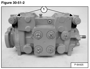
Locate the two hydraulic controllers (Item 1) [Figure 30-51-2] on the hydrostatic pumps.
Disconnect all of the electrical harness connectors (Item 1) [Figure 30-51-3] from the loader harness.
Removal:
Remove the four mount bolts (Item 1) [Figure 30-51-4] from the hydraulic controller.
Remove the controller (Item 1) [Figure 30-51-5] from the pump.
Remove the controller gaskets (Item 2) [Figure 30-51-5] from the pump.
Installation:
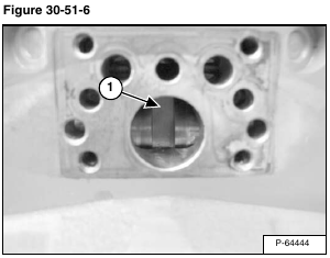
Be sure the feedback lever (Item 3) [Figure 30-51-5] is in the center of the servo piston groove (Item 1) [Figure 30-51-6].
Use a small amount of grease on a new gasket and install the gasket on the hydraulic controller (Item 1) [Figure 30-51-5].
Be sure the pump surface is clean.
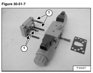
Alternately tighten bolts (Item 1) [Figure 30-51-7] to 7.7 ft.-lb. (10,4 Nm) torque. Ensure bolts are tight to specifications.
NOTE: When a hydraulic controller is replaced, the hydrostatic pumps must be calibrated. (See Hydraulic Controller Neutral Adjustment on Page 30-41-28.)
With the engine running and the loader on jack stands:
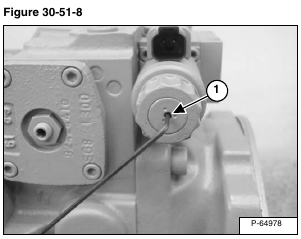
Bleed the trapped air in the controller by loosening the small set screw (Item 1) [Figure 30-51-8] a maximum of 2 turns. Leave the screw loose until oil comes dripping out of the set screw. Tighten set screw to 18 in.-lb. (2 N•m) torque.
Repeat the bleeding procedure for all of the solenoids.


