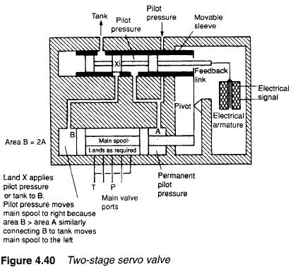
Servo valves are a close relative of the proportional valve and are based on an electrical torque motor which produces a small deflection proportional to the electrical current through its coil. They commonly use feedback between the main and pilot spools to give precise control. A typical device is shown on Figure 4.40. This consists of a small pilot spool connected directly to the torque motor. The pilot spool moves within a sliding sleeve, mechanically linked to the main spool.
The fight-hand end of the main spool is permanently connected to the pilot pressure line, but because of the linkage rod its area is reduced to an annulus of area A. Pressure at the left-hand end of the spool is controlled by the pilot valve. There is no area restriction at this end, and the valve is designed such that the spool has an area of 2A.
If the same pressure P is applied to both ends, the spool experiences a left force of P x A and a right force of 2P x A causing a net force of P x A to the fight, resulting in a shift of the spool to the fight.
If a pressure of P is applied to the right-hand end and 0.5P is applied to the left-hand end, equal and opposite forces of P x A result and the valve spool is stationary.
With a pressure of P on the right-hand end and a pressure less than 0.5P on the left-hand end, net force is to the left and the valve spool moves in that direction.
The pilot valve can thus move the main spool in either direction, in a controlled manner, by varying pressure at left-hand end of the main spool from zero to full pilot pressure.
The mechanical linkage between main spool and pilot sleeve controls the flow of fluid between pilot valve and main valve, and hence controls pressure at the left-hand end of the main spool. Suppose the electrical control signal causes the pilot spool to shift left. This increases the pressure causing the main valve to shift right which in turn pushes the sleeve left. The main valve stops moving when the hole in the pilot sleeve exactly aligns with the land on the pilot spool. A change in electrical signal moving the pilot spool to the fight reduces pressure at the left-hand end of the main spool by bleeding fluid back to the tank. This causes the main spool to move left until, again, pilot sleeve and pilot lands are aligned. The main valve spool thus follows the pilot spool with equal, but opposite movements.
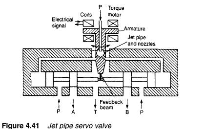
Figure 4.41 illustrates the construction of a different type of servo valve, called a jet pipe servo. Pilot pressure is applied to a jet pipe which, with a 50% control signal, directs an equal flow into two pilot lines. A change of control signal diverts the jet flow giving unequal flows and hence unequal pressures at ends of the main spool. The main spool is linked mechanically to the jet pipe, causing it to move to counteract the applied electrical signal. Spool movement ceases when the jet pipe is again centrally located over the two pilot pipes. This occurs when the main valve spool movement exactly balances the electrical control signal.
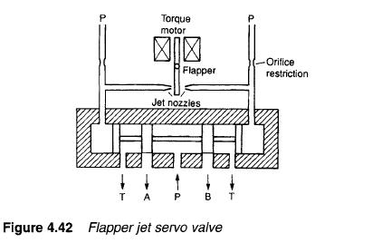
The servo valve in Figure 4.42 is called a flapper servo and is really the inverse of the jet pipe servo. Here, pilot pressure is applied to both ends of the main spool and linked by orifices to small jets playing to a flapper which can be moved by the electrical control signal. Pressure at each end of the main spool (and hence spool movement) is determined by the flow out of each jet which, in turn, is determined by flapper position and electrical control signal.
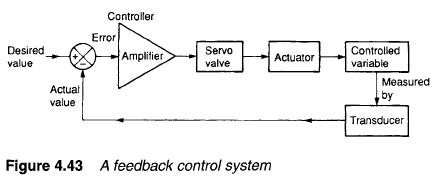
Servo valves are generally used as part of an external control loop in a feedback control system. The principle of a feedback control system is shown in Figure 4.43 where some plant variable (velocity or position, for example) is to be controlled. The plant variable is measured by a suitable transducer, and electronically compared with the desired value to give an error signal. This is amplified and used as the control signal for the servo valve.
It can be appreciated that, with small movements of the pilot spool (in Figure 4.40) and the fine jets (in Figures 4.41 and 4.42), servo valves are particularly vulnerable to dirt. Cleanliness is important in all aspects of pneumatics and hydraulics, but is overwhelmingly important with servo valves. A filtration level of 10um is normally recommended (compared with a normal filtration of 25 um for finite position valve systems).
Servo valves which are stationary for the majority of time can stick in position due to build-up of scum around the spool. This is known, aptly, as stiction. A side effect of stiction can be a deadband where a large change of control signal is needed before the valve responds at all.
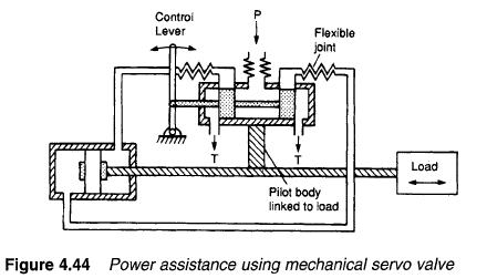
Figure 4.44 shows a purely mechanical servo used as a mechanical booster to allow a large load to be moved with minimal effort. The pilot valve body is connected to the load, and directs fluid to the fixed main cylinder. The cylinder, and hence the load, moves until pilot spool and cylinder are again aligned. Variations on the system in Figure 4.44 are used for power steering in motor cars.
