NOTE: The key must be put in the ON position when checking for power in circuits.
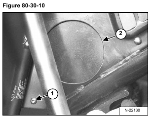
Remove the mount bolt (Item 1) [Figure 80-30-10] from the left side cab access cover.
Remove the access cover (Item 2) [Figure 80-30-10] from the loader.
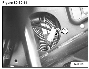
Disconnect the blower fan wiring connector (Item 1) [Figure 80-30-11] from the loader wiring harness.
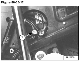
Check the loader harness (Item 1) [Figure 80-30-12] for voltage. The voltage should be 12 volts.
If there is no voltage at the wiring harness, check the harness for broken wires or blown fuse.
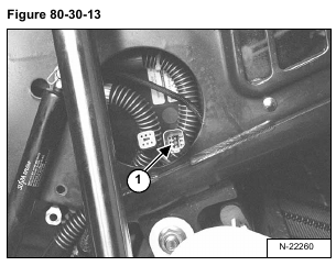
If there is voltage at the wiring harness, check the resistance to the blower fan at the blower fan wiring connector (Item 1) [Figure 80-30-13].
If there is no resistance value replace the blower fan. (See Removal And Installation on Page 80-70-1.)
If there is a resistance value check the climate controls at the control panel inside the loader cab.
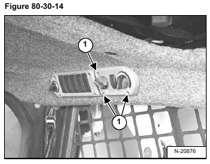
Remove the three mount screws (Item 1) [Figure 80-30-14] from the cab control panel.
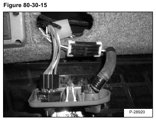
Remove the control panel and wiring harness from the cab [Figure 80-30-15].
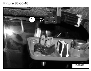
Disconnect the loader wiring harness (Item 1) [Figure 80-30-16] from the blower switch.
Check the loader harness for voltage. The voltage should be 12 volts.
If there is no voltage at the wiring harness, check the harness for broken wires or blown fuse.
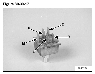
If there is voltage at the wiring harness, check the blower switch [Figure 80-30-17] for resistance.
With the switch in the OFF position, there should be resistance between L terminal and the H terminal frame.
With the switch in the 1 position, there should be resistance between C terminal and the B terminal, between the C terminal and the L terminal and also between the B terminal and the L terminal frame [Figure 80-30-17].
With the switch in the 2 position, there should be resistance between C terminal and the B terminal, between the C terminal and the M terminal and also between the B and the M terminal frame [Figure 80-30-17].
With the switch in the 3 position, there should be resistance between C terminal and the B terminal, between the C terminal and the H terminal and also between the B terminal and the H terminal frame [Figure 80-30-17].
If any of the above resistance tests fail, replace the blower switch.
If the above resistance tests are good, check the potentionmeter.
The potentiometer will affect the operation of the heater.
If heater valve does not open, or close, check the potentiometer.
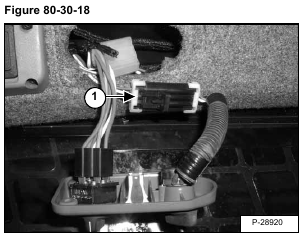
At the loader cab, disconnect the loader harness (Item 1) [Figure 80-30-18] from the potentiometer.
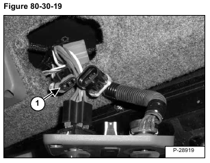
Check the loader harness (Item 1) [Figure 80-30-19] for voltage. The voltage should be 12 volts.
If there is no voltage at the wiring harness, check the harness for broken wires or blown fuse.
If there is voltage at the wiring harness, check the potentiometer [Figure 80-30-20] for resistance.
The resistance should be 10 K Ohm’s between wire terminal A and wire terminal C frame [Figure 80-30-20].
If no resistance is found replace the potentiometer.
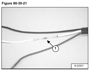
The white wire B, (Item 1) [Figure 80-30-21], on the potentiometer, is a resistor wire.
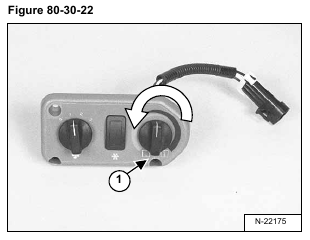
To check the resistance of the white wire, turn the potentiometer control (Item 1) [Figure 80-30-22] to the full A/C position.
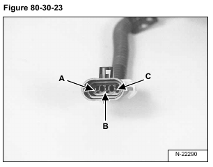
The resistance between the wire terminal A and wire terminal B frame [Figure 80-30-23] should be approximately 49 K Ohm’s.
Check the resistance between the wire terminal C and wire terminal B frame [Figure 80-30-23] should be approximately 39 K Ohm’s.
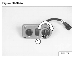
To check the resistance of the white wire, turn the potentiometer control (Item 1) [Figure 80-30-24] to the full Heater position.
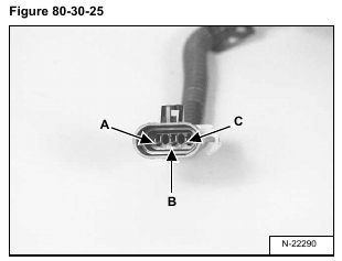
Check the resistance between the wire terminal A and wire terminal B frame [Figure 80-30-25] should be approximately 39 K Ohm’s.
Check the resistance between the wire terminal C and wire terminal B frame [Figure 80-30-25] should be approximately 49 K Ohm’s.
If the resistance is not found replace the potentiometer.
