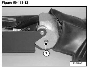
Remove one of the two mounting screws (Item 1) [Figure 50-113-12] from the handle sensor.
Installation: Tighten bolt to 32-38 in.-lbs. (3,6-4,3 Nm) torque.
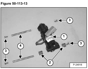
Remove the handle sensor (Item 1) [Figure 50-113-13] from the handle assembly.
NOTE: The handle sensor (Item 1) [Figure 50-113-13] can only be replaced as a complete assembly.
Check the spacers (Item 2), screws (Item 3), mounting pins (Item 4) [Figure 50-113-13] and replace as needed.
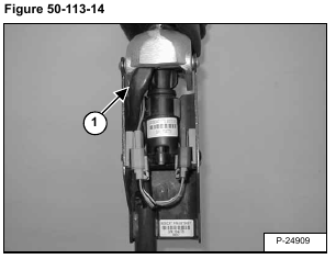
Installation: When installing the handle sensor into the control handle, check the routing of the switch handle
wire harness (Item 1) [Figure 50-113-14] to assure proper return of the control handle to neutral and minimize harness movement.
NOTE: The calibration procedure must be followed when replacing handle sensor, foot pedal
sensor, actuator or ACS Controller. (See Calibration Of The ACS System on Page 60-123-14.)


