NOTE: (See Gearbox Disassembly on Page 70-60-7.) when ordering parts for the Fan Gearbox.
NOTE: Do not install the seals and cap in the housing until after the backlash has been checked.
NOTE: Use care when pressing the bearings into the aluminum housing. The housing can be damaged if too much pressure is used.
NOTE: For procedures requiring the use of LOCTITE #242 adhesive, thoroughly clean and dry affected parts before the application of LOCTITE #242.
Long Housing
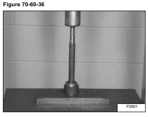
Press a bearing on the short keyed end of the long shaft [Figure 70-60-36].
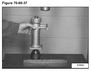
Install the long housing on the shaft [Figure 70-60-37].
Be sure the bearing is seated in the bore at the lower end of the housing.
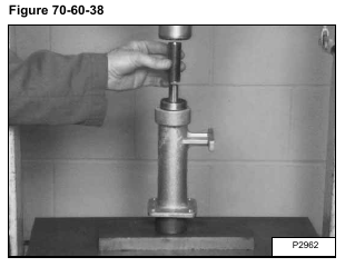
Install a bearing on the long keyed end of the shaft [Figure 70-60-38].
Support the lower bearing and press the other bearing in the housing until the bearings seat in the housing [Figure 70-60-38].
Install on the bearing, the same number and size shims that were removed during disassembly [Figure 70-60-39].
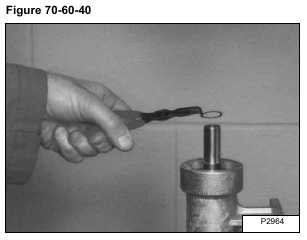
Install the small snap ring in the groove above the shims [Figure 70-60-40].
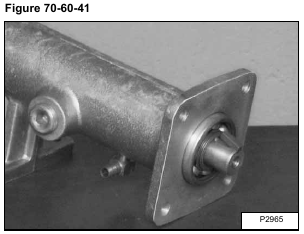
Install the gear key in the flange end of the shaft [Figure 70-60-41].
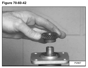
Align the key and gear. While supporting the bearing on the other end, press the gear on the shaft until it seats against the bearing [Figure 70-60-42].
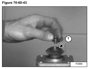
Install the washer (Item 1) [Figure 70-60-43].
Put liquid adhesive (LOCTITE #242) on the screw threads. Install and tighten the screw [Figure 70-60-43].
Short Housing
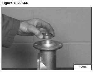
Install a bearing in the flanged end of the housing [Figure 70-60-44].
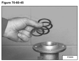
Install the large shims on the bearing (flanged end) [Figure 70-60-45]
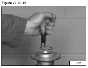
Install the large snap ring in the groove above the shims [Figure 70-60-46].
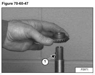
Install the short key (Item 1) [Figure 70-60-47].
Align and press the gear on the shaft (teeth toward the tapered end of the shaft) [Figure 70-60-47].
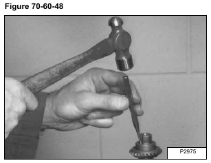
After the gear is seated, drive the key down inside the gear key way [Figure 70-60-48].
NOTE: This will prevent damage to the shims when the bearing is installed later.
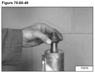
Install the shaft in the housing, tapered end in the bearing at the round flange end of the housing [Figure 70-60-49].
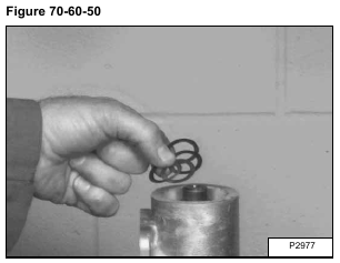
Install on the shaft, the same number and size shims that were removed during disassembly [Figure 70-60-50].
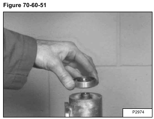
Install a bearing on the gear end of the shaft [Figure 70-60-51].
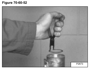
Install the snap ring in the groove above the bearing [Figure 70-60-52].
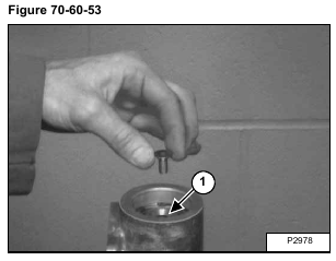
Install the washer (Item 1) on the shaft. Put liquid adhesive (LOCTITE #242) on the screw threads and install the screw [Figure 70-60-53].
