NOTE: For procedures requiring the use of LOCTITE #242 adhesive, thoroughly clean and dry affected parts before the application of LOCTITE #242.
The backlash tolerance between the gears should be 0.005-0.008 inch (0,127-0,203 mm).
To check the gear backlash use the following procedure:
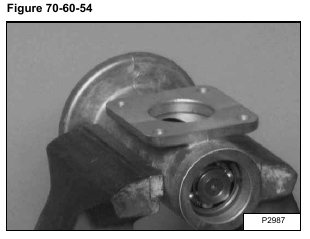
Put the short housing in a vise, square flange facing up as shown [Figure 70-60-54].
Install the same size and number of square shims (if present during disassembly) between the two housings [Figure 70-60-55].
Set the long housing on the short housing with the sealant (LOCTITE #242) which is a gasket eliminator that cures to flexible seal between the mounting surfaces.
NOTE: If square shims are used, put a small amount of (LOCTITE #242) on both sides of all shims.
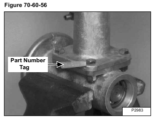
Install the four mounting bolts through the flange holes [Figure 70-60-56].
Install the part number tag [Figure 70-60-56].
Install and tighten the nuts to 25-28 ft.-lbs. (34-38 Nm) torque.
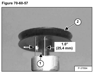
Install the long key (Item 1) and the pulley (Item 2) [Figure 70-60-57].
Install a bolt in the set screw hole to maintain a 1.0 inch (25,4 mm) distance from the shaft center to the bolt head (to be used with a dial indicator) [Figure 70-60-57].
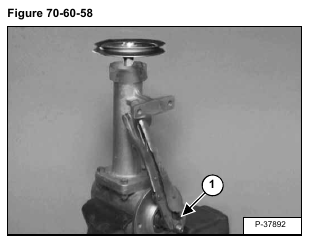
Put the fan nut (Item 1) [Figure 70-60-58] on the shaft and tighten snugly.
Install a locking pliers on the fan nut and support the handle against the long housing [Figure 70-60-58].
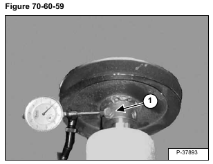
Using a magnetic based dial indicator mounted on a bench vise, touch the dial stem on the bolt (Item 1) [Figure 70-60-59].
Hold the locking pliers against the long housing and rotate the pulley back and forth to read the dial gauge [Figure 70-60-59].
If the backlash is GREATER than 0.008 inch (0,203 mm), do the following:
1. Remove a square shim(s) (if present) between the two housings.
2.Remove a large shim(s) from the tapered end of the short shaft and add a small shim (s) of the same thickness between the bearing and the gear on the screw end of the shaft.
If the backlash is LESS than 0.005 inch (0,127 mm) do the following:
1. Add a square shim(s) between the two housings.
2. Remove a small shim(s) between the bearing and the gear on the screw end of the short shaft and add a large shim(s) of the same thickness between the snap ring and the bearing on the tapered end of the shaft.
When the backlash is correct, install the seals, cap and gear oil as follows:
Remove the bolts from the flanges and separate the two housings.
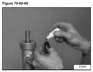
Put liquid adhesive (LOCTITE #242) on the outside diameter of the seal(s) [Figure 70-60-60].
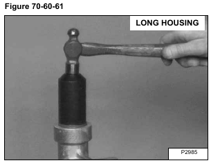
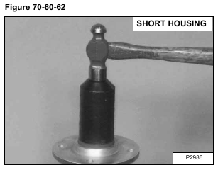
Install the seal(s) flush with the housing surface [Figure 70-60-61] & [Figure 70-60-62].
Clean any oil from the flange surface.
Install the long housing on the short housing flange.
Install the four bolts and part number tag.
Install and tighten the nuts to 25-28 ft.-lbs. (34-38 Nm) torque.
NOTE: When filling the fan gearbox with oil, be sure the level does not go above the top of the shaft in the gearbox. Use a light colored 90W gear lube.
