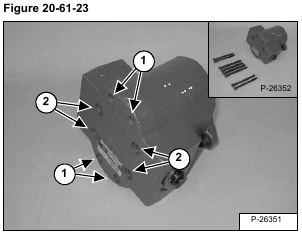
Mark the pump sections for correct assembly [Figure 20-61-23].
Remove the four smaller pump housing bolts (Item 1) [Figure 20-61-23].
Remove the four larger pump housing bolts (Item 2) [Figure 20-61-23].
Installation: Tighten the four smaller bolts (Item 1) to 30 ft.-lbs. (40,7 Nm) torque. Tighten the four larger bolts
(Item 2) [Figure 20-61-23] to 54 ft.-lbs. (73,2 Nm) torque.
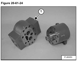
Remove the pump end section (Item 1) [Figure 20-61-24].
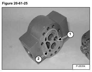
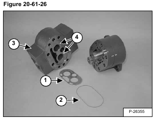
Remove the wear plate (Item 1) [Figure 20-61-25] & [Figure 20-61-26] and section seal (Item 2) [Figure 20-
61-25] & [Figure 20-61-26] from the pump end section.
NOTE: Position wear plate (Item 1) [Figure 20-61-26] inlets and traps as shown with bronze side toward gears.
NOTE: Inspect the pump end section (Item 3) and bushings (Item 4) [Figure 20-61-26]. If excessive wear or damage is visible, the pump must be replaced.
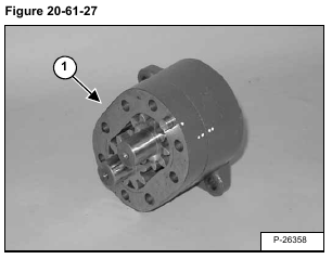
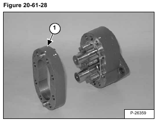
Remove the pump center section (Item 1) [Figure 20-61-27] & [Figure 20-61-28] from the pump end section.
NOTE: Inspect the pump center section (Item 1) [Figure 20-61-28]. If excessive wear or damage is visible, the pump must be replaced.
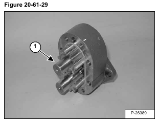
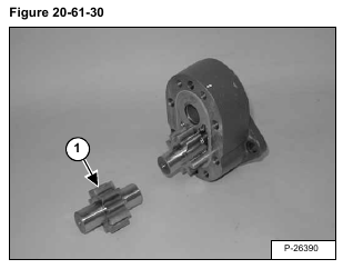
Remove the idler gear (Item 1) [Figure 20-61-29] & [Figure 20-61-30].
NOTE: Inspect the idler gear (Item 1) [Figure 20-61-30]. If excessive wear or damage is visible, the
pump must be replaced.
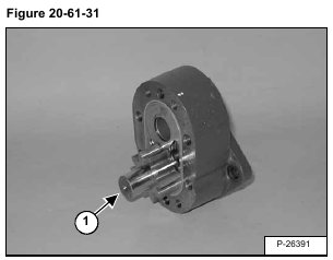
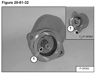
To remove the drive gear (Item 1) [Figure 20-61-31] from the pump end section, locate and remove the retaining
ring (Item 1) [Figure 20-61-32] from the spline end of the drive gear.
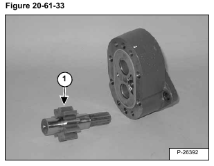
Remove the drive gear (Item 1) [Figure 20-61-33] from the pump end section.
NOTE: Inspect the drive gear (Item 1) [Figure 20-61-33]. If excessive wear or damage is visible, the
pump must be replaced.
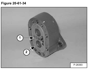
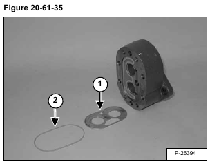
Remove the wear plate (Item 1) [Figure 20-61-34] & [Figure 20-61-35] and section seal (Item 2) [Figure 20-
61-34] & [Figure 20-61-35] from the pump end section.
NOTE: Position wear plate (Item 1) [Figure 20-61-35] inlets and traps as shown with bronze side toward gears.
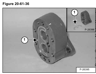
Remove the load seal (Item 1) [Figure 20-61-36].
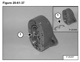
Remove the pre-load seal (Item 1) [Figure 20-61-37].
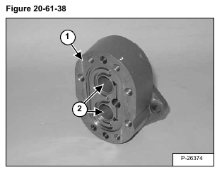
NOTE: Inspect the pump end section (Item 1) and bushings (Item 2) [Figure 20-61-38] . If excessive wear or damage is visible, the pump must be replaced.
Reverse the disassembly procedure to assemble the hydraulic pump.
