Clean all parts with solvent and dry with compressed air.
Put grease on O-rings.
Lubricate parts with oil.
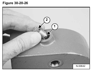
Install the poppet (Item 1) and spring (Item 2) [Figure 30-20-26] in the low pressure relief port in the end cover.
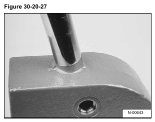
Install the new O-ring on the plug and tighten to 300 in.- lbs. (34 Nm) torque [Figure 30-20-27].
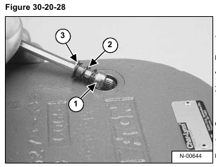
Install the poppet (Item 1), the spring (Item 2) and the spring sleeve (Item 3) [Figure 30-20-28] in the end cover.
NOTE: The tapered end of the poppet must face towards the shuttle valve.
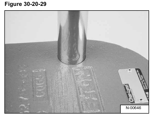
Install a new O-ring on the plug [Figure 30-20-29] and tighten to 260 in.-lbs. (41 Nm) torque.
NOTE: Always use new O-rings and seals when assembling the motor. Put a small amount of grease on all the O-rings and seals for easier installation.
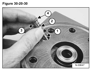
Install the shuttle valve (Item 1), poppet (Item 2), spring (Item 3) and spring sleeve (Item 4) [Figure 30-20-30] in
the port hole in the end cap.
NOTE: The tapered end of the poppet must face towards the shuttle valve.
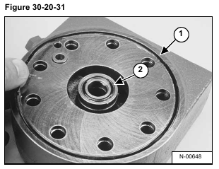
Install the square cut seal (Item 1) and small O-ring (Item 2) [Figure 30-20-31] in the end cover.
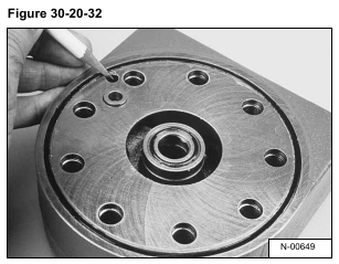
Mark the case drain port location on the outside of the end cover for ease of assembly [Figure 30-20-32].
Align the case drain ports in the valve plate with the case drain port in the end cover [Figure 30-20-33].
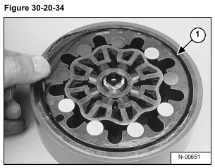
Install the large square cut seal (Item 1) [Figure 30-20-34] in gerolor assembly.
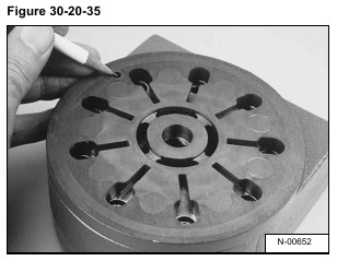
Mark the case drain port location on the outside edge of the valve plate as shown [Figure 30-20-35].
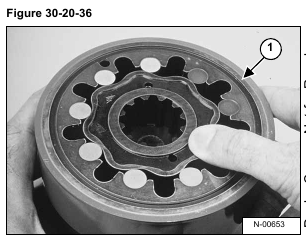
Install the gerolor assembly (Item 1) [Figure 30-20-36] by aligning the case drain hole with the case drain hole in the valve plate.
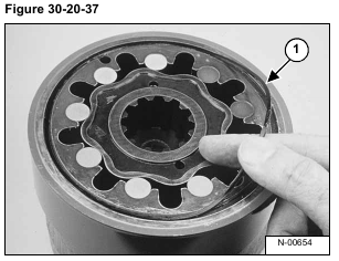
Install the square cut seal (Item 1) [Figure 30-20-37] in the gerolor outer ring.
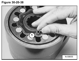
Install the two check balls (Item 1) [Figure 30-20-38] in their bores in the gerolor star.
Install the main drive (Item 1) [Figure 30-20-39] in the gerolor (as shown).
NOTE: Whenever the main drive is not symmetrical, the smallest end of the main drive must be installed into the gerolor star.
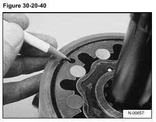
Mark the case drain hole on the outer ring of the gerolor (as shown) [Figure 30-20-40].
Align the case drain holes and install the balance plate (Item 1) [Figure 30-20-41] on the gerolor assembly.
Install the seal (Item 1) [Figure 30-20-42] (as shown).
Install the square cut seal (Item 1), seal (Item 2), back-up seal (Item 3), seal (Item 4) and back-up ring (Item 5)
[Figure 30-20-43] in the mounting flange.
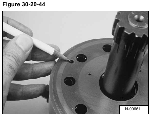
Mark the case drain holes on the side of the balance plate [Figure 30-20-44].
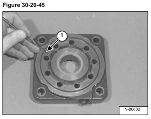
Align the case drain port (Item 1) [Figure 30-20-45] in the mounting flange with the case drain port in the
balance plate (as shown).
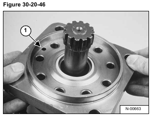
Align the case drain port (Item 1) [Figure 30-20-46] and install the mounting flange on the balance plate.
Be careful not to displace the seals and back-up rings.
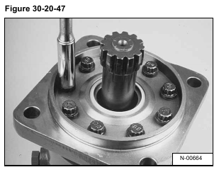
Install the nine bolts into the motor. Make sure all the parts are in correct alignment [Figure 30-20-47].
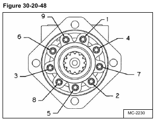
1. Tighten the bolts to 45-55 ft.-lbs. (61-75 Nm) torque as shown [Figure 30-20-48].
2. Tighten the bolts to 55-65 ft.-lbs. (75 -88 Nm) torque as shown [Figure 30-20-48].
NOTE: To prevent damage to the balance plate, never lift or support the motor by the center shaft.
