Drain the oil from the motor.
Seal all open ports and clean the motor with solvent.
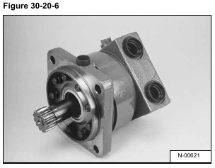
Put a mark across the sections of the motor for correct assembly [Figure 30-20-6].
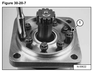
Remove the nine bolts (Item 1) [Figure 30-20-7] from the motor.
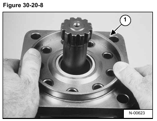
Lift and remove the mounting flange (Item 1) [Figure 30-20-8] from the motor.
NOTE: Do not scratch or damage the surfaces of the motor sections. Always put them on a soft surface.
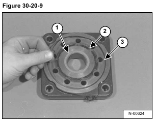
Turn the mounting flange over and remove the O-ring and back-up ring (Item 1), the seal and back-up ring (Item 2),
and the square-cut seal (Item 3) [Figure 30-20-9].
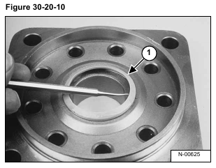
Turn the mounting flange backover and remove the seal (Item 1) [Figure 30-20-10] from the mounting flange.
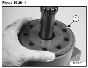
Remove the balance plate (Item 1) [Figure 30-20-11] from the gerolor assembly.
Remove the main drive (Item 1) [Figure 30-20-12] from the gerolor assembly.
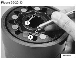
Remove the two check balls (Item 1) [Figure 30-20-13] from the gerolor.
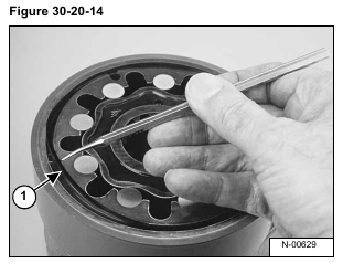
Remove the square cut seal (Item 1) [Figure 30-20-14] from the gerolor.
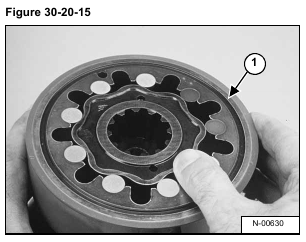
Remove the gerolor assembly (Item 1) [Figure 30-20-15].
NOTE: Care should be taken to keep the gerolor assembly together.
NOTE: If rollers are removed, put them back in their original bore with the correct orientation.
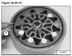
Carefully turn the gerolor assembly over and remove the square cut seal (Item 1) [Figure 30-20-16].
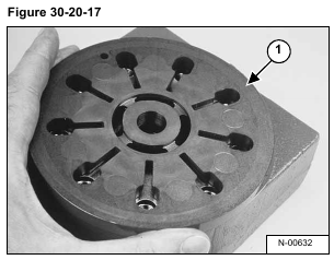
Remove the valve plate (Item 1) [Figure 30-20-17] from the end cap.
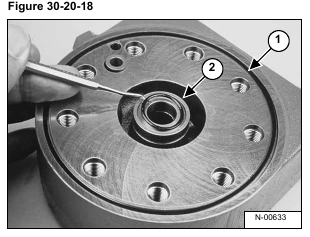
Remove the square cut seal (Item 1) and small O-ring (Item 2) [Figure 30-20-18] from the end cap.
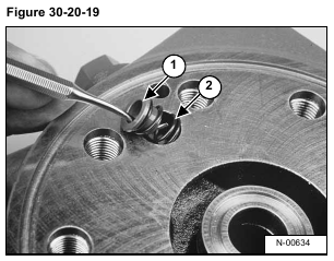
Remove the spring seat (Item 1) and spring (Item 2) [Figure 30-20-19].
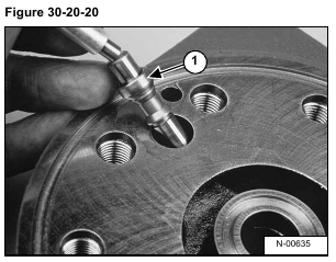
Remove the poppet and shuttle valve (Item 1) [Figure 30-20-20].
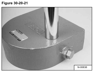
Turn the end cover over and remove the shuttle valve plug from the end cover [Figure 30-20-21].
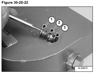
Remove the spring sleeve (Item 1), spring (Item 2) and poppet (Item 3) [Figure 30-20-22].
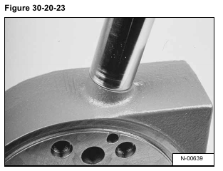
Remove the low pressure relief valve plug from the side of the end cover [Figure 30-20-23].
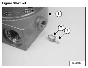
Remove the spring (Item 1) and poppet (Item 2) from the end cover (Item 3) [Figure 30-20-24].
NOTE: The relief pressure is factory set and must not be changed. Shims may or may not have been
used at the factory for setting the pressure. If shims are present, make sure they are reinstalled during assembly.
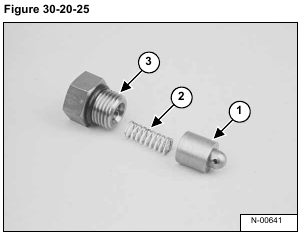
The low pressure relief valve is made up of the poppet (Item 1), the spring (Item 2) and the plug assembly (Item
3) [Figure 30-20-25].
