Remove the control valve from the loader.
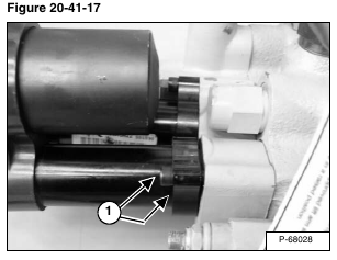
Remove the two mount bolts (Item 1) [Figure 20-41-17] from the lift actuator.
Installation: Tighten the mounting bolts to 90 – 100 in.-lb. (10,2 – 11,3 N•m) torque.
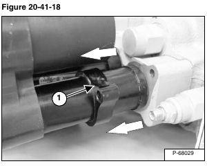
Slide the actuator mount bracket (Item 1) [Figure 20-41-18] away from the control valve.
Pull the actuator away from the control valve [Figure 20-41-18].
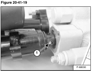
Using a drift pin and a hammer, remove the actuator linkage pin (Item 1) [Figure 20-41-19] from the actuator and the lift spool.
Remove the actuator and linkage pin from the valve.
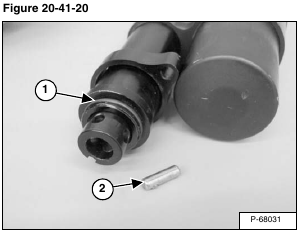
Inspect the O-ring (Item 1) [Figure 20-41-20] on the nose of the actuator, and replace as needed.
Check the linkage pin (Item 2) [Figure 20-41-20] and replace as needed.
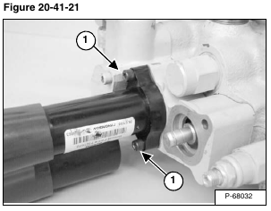
Remove the two mount bolts (Item 1) [Figure 20-41-21] from the tilt actuator.
Installation: Tighten the mounting bolts to 90 – 100 in.-lb. (10,2 – 11,3 N•m) torque.
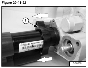
Slide the actuator mount bracket (Item 1) [Figure 20-41-22] away from the control valve.
Pull the actuator away from the control valve [Figure 20-41-22].
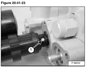
Using a drift pin and a hammer, remove the actuator linkage pin (Item 1) [Figure 20-41-23] from the actuator and the tilt spool.
Remove the actuator and linkage pin from the valve.
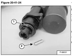
Inspect the O-ring (Item 1) [Figure 20-41-24] on the nose of the actuator, and replace as needed.
Check the linkage pin (Item 2) [Figure 20-41-24] and replace as needed.
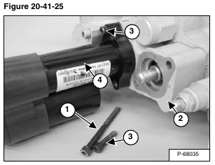
NOTE: The two longer bolts (Item 1) are used to mount the lift actuator and end cap (Item 2) to the control valve.
The two shorter mount bolts (Item 3) are used to mount the tilt actuator (Item 4) [Figure 20-41-25] to the end cap.
Installation: Tighten the mounting bolts to 90 – 100 in.-lb.
(10,2 – 11,3 N•m) torque (Item 1) [Figure 20-41-25]
