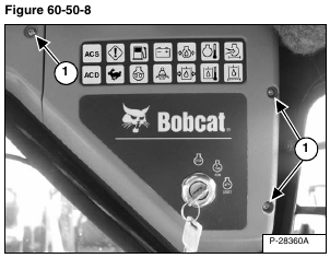
Remove the three mounting bolts (Item 1) [Figure 60-50-8].
Installation: Be careful to not overtighten the instrument panel mounting bolts to prevent stripping of the threaded holes in the panels.
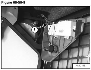
Pull the right instrument panel down and disconnect the wire harness connector (Item 1) [Figure 60-50-9] from the panel.
Remove the panel from the loader cab.
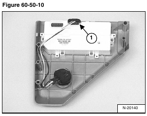
Disconnect the key switch wiring harness (Item 1) [Figure 60-50-10] from the back of the control panel.
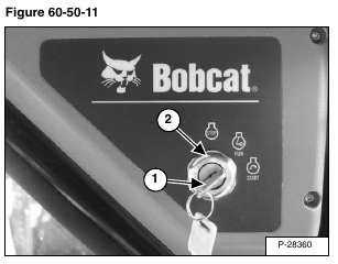
Remove the ignition key (Item 1) from the switch.
Remove the ignition switch retaining nut (Item 2) [Figure 60-50-11] from the switch.
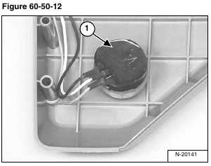
Remove the ignition switch (Item 1) [Figure 60-50-12] from the control panel.
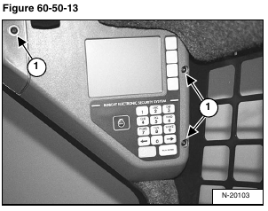
Remove the three mounting bolts (Item 1) [Figure 60-50-13].
Installation: Be careful to not overtighten the instrument panel mounting bolts to prevent stripping of the threaded holes in the panels.
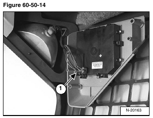
Pull the right instrument panel down and disconnect the wire harness connector (Item 1) [Figure 60-50-14] from the panel.
Remove the panel from the loader cab.
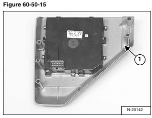
NOTE: The instrument panel (Item 1) [Figure 60-50-15] must be replaced as a complete unit.
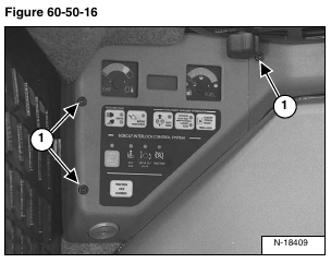
Remove the three mounting bolts (Item 1) [Figure 60-50-16].
Installation: Be careful to not overtighten the instrument panel mounting bolts to prevent stripping of the threaded holes in the panels.
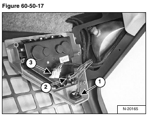
Pull the left instrument panel down and disconnect the wire harness connector (Item 1) [Figure 60-50-17] from the loader alarm.
Disconnect the wire harness connector (Item 2) [Figure 60-50-17] from the loader instrument panel.
NOTE: The wiring harness (Item 3) [Figure 60-50-17] is an optional accessory harness.
Remove the instrument panel from the loader.
Remove the left side instrument panel.
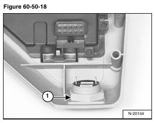
Remove the retaining nut (Item 1) [Figure 60-50-18] from the loader alarm.
Remove the alarm from the loader instrument panel.
