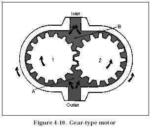
Figure 4-10 shows a gear-type motor. Both gears are driven gears, but only one is connected to the output shaft. Operation is essentially the reverse of that of a gear pump. Flow from the pump enters chamber A and flows in either direction around the inside surface of the casing, forcing the gears to rotate as indicated. This rotary motion is then available for work at the output shaft.
