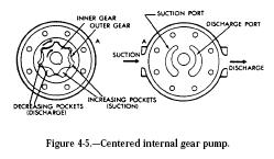
Another design of internal gear pump is illustrated in figures 4-5 and 4-6. This pump consists of a pair of gear-shaped elements, one within the other, located in the pump chamber. The inner gear is connected to the drive shaft of the power source.
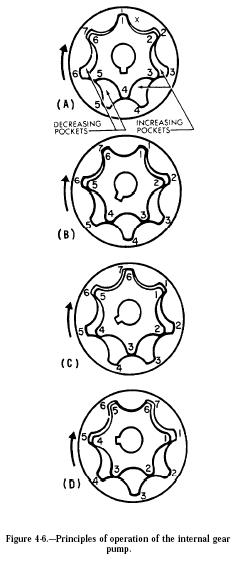
The operation of this type of internal gear pump is illustrated in figure 4-6. To simplify the explanation, the teeth of the inner gear and the spaces between the teeth of the outer gear are numbered. Note that the inner gear has one less tooth than the outer gear. The tooth form of each gear is related to that of the other in such a way that each tooth of the inner gear is always in sliding contact with the surface of the outer gear. Each tooth of the inner gear meshes with the outer
gear at just one point during each revolution. In the illustration, this point is at the X. In view A, tooth 1 of the inner gear is meshed with space 1 of the outer gear. As the gears continue to rotate in a clockwise direction and the teeth approach point X, tooth 6 of the inner gear will mesh with space 7 of the outer gear, tooth 5 with space 6, and so on. During this revolution, tooth 1 will mesh with space 2; and during the following revolution, tooth 1 will mesh with space 3. As a result, the outer gear will rotate at just six-sevenths the speed of the inner gear.
At one side of the point of mesh, pockets of increasing size are formed as the gears rotate, while on the other side the pockets decrease in size. In figure 4-6, the pockets on the right-hand side of the drawings are increasing in size toward the bottom of the illustration, while those on the left-hand side are decreasing in size toward the top of the illustration. The intake side of the pump would therefore be on the right and the discharge side on the left. In figure 4-5, since the right-hand side of the drawing was turned over to show the ports, the intake and discharge appear reversed. Actually, A in one drawing covers A in the other.

