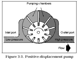
In most rotary hydraulic pumps (Figure 3-3), the design is such that the pumping chambers increase in size at the inlet, thereby creating a vacuum. The chambers then decrease in size at the outlet to push fluid into a system. The vacuum at the inlet is used to create a pressure difference so that fluid will flow from a reservoir to a pump. However, in many systems, an inlet is charged or supercharged; that is, a positive pressure rather than a vacuum is created by a pressurized reservoir, a head of fluid above the inlet, or even a low-pressure-charging pump. The essentials of any hydraulic pump are—
• A low-pressure inlet port, which carrys fluid from the reservoir.
• A high-pressure outlet port connected to the pressure line.
• Pumping chamber(s) to carry a fluid from the inlet to the outlet port.
• A mechanical means for activating the pumping chamber(s).
Pumps may be classified according to the specific design used to create the flow of a liquid. Most hydraulic pumps are either centrifugal, rotary, or reciprocating.
a. Centrifugal Pump. This pump generally is used where a large volume of flow is required at relatively low pressures. It can be connected in series by feeding an outlet of one pump into an inlet of another. With this arrangement, the pumps can develop flow against high pressures. A centrifugal pump is a nonpositive-displacement pump, and the two most common types are the volute and the diffuser.
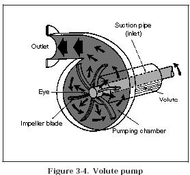
(1) Volute Pump (Figure 3-4). This pump has a circular pumping chamber with a central inlet port (suction pipe) and an outlet port. A rotating impeller is located in a pumping chamber. A chamber between the casing and the center hub is the volute. Liquid enters a pumping chamber through a central inlet (or eye) and is trapped between the whirling impeller blades. Centrifugal force throws a liquid outward at a high velocity, and a contour of a casing directs a moving liquid through an outlet port.
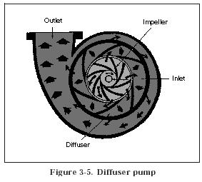
(2) Diffuser Pump (Figure 3-5). Similar to a volute type, a diffuser pump has a series of stationary blades (the diffuser) that curve in the opposite direction from whirling impeller blades. A diffuser reduces the velocity of a liquid, decreases slippage, and increases a pump’s ability to develop flow against resistance.
b. Rotary Pump. In this positive displacement-type pump, a rotary motion carries a liquid from a pump’s inlet to its outlet. A rotary pump is usually classified according to the type of element that actually transmits a liquid, that is, a gear-, vane-, or piston-type rotary pump.
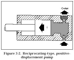
c. Reciprocating Pump. A reciprocating pump depends on a reciprocating motion to transmit a liquid from a pump’s inlet to its outlet. Figure 3-2, shows a simplified reciprocating pump. It consists of a cylinder that houses a reciprocating piston, Figure 3-2, 1; an inlet valve, Figure 3-2, 2; and an outlet valve, Figure 3-2, 3, which direct fluid to and from a cylinder. When a piston moves to the left, a partial vacuum that is created draws a ball off its seat, allowing a liquid to be drawn through an inlet valve into a cylinder. When a piston moves to the right, a ball reseats and closes an inlet valve. However, the force of a flow unseats a ball, allowing a fluid to be forced out of a cylinder through an outlet valve.


