Gear pumps are external, internal, or lobe types.
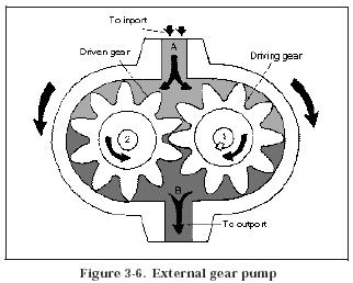
a. External. Figure 3-6 shows the operating principle of an external gear pump. It consists of a driving gear and a driven gear enclosed in a closely fitted housing. The gears rotate in opposite directions and mesh at a point in the housing between the inlet and outlet ports. Both sets of teeth project outward from the center of the gears. As the teeth of the two gears separate, a partial vacuum forms and draws liquid through an inlet port into chamber A. Liquid in chamber A is trapped between the teeth of the two gears and the housing so that it is carried through two separate paths around to chamber B. As the teeth again mesh, they produce a force that drives a liquid through an outlet port.
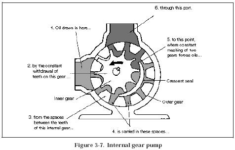
b. Internal. Figure 3-7 shows an internal gear pump. The teeth of one gear project outward, while the teeth of the other gear project inward toward the center of the pump. One gear wheel stands inside the other. This type of gear can rotate, or be rotated by, a suitably constructed companion gear. An external gear is directly attached to the drive shaft of a pump and is placed off-center in relation to an internal gear. The two gears mesh on one side of a pump chamber,
between an inlet and the discharge. On the opposite side of the chamber, a crescents haped form stands in the space between the two gears to provide a close tolerance.
The rotation of the internal gear by a shaft causes the external gear to rotate, since the two are in mesh. Everything in the chamber rotates except the crescent, causing a liquid to be trapped in the gear spaces as they pass the crescent. Liquid is carried from an inlet to the discharge, where it is forced out of a pump by the gears meshing. As liquid is carried away from an inlet side of a pump, the pressure is diminished, and liquid is forced in from the supply source. The size of the crescent that separates the internal and external gears determines the volume delivery of
this pump. A small crescent allows more volume of a liquid per revolution than a larger crescent.
c. Lobe. Figure 3-8 shows a lobe pump. It differs from other gear pumps because it uses lobed elements instead of gears. The element drive also differs in a lobe pump. In a gear pump, one gear drives the other. In a lobe pump, both elements are driven through suitable external gearing.


