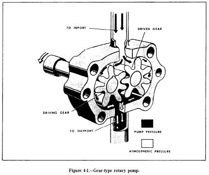
The spur gear pump (fig. 4-1) consists of two meshed gears which revolve in a housing. The drive gear in the illustration is turned by a drive shaft which is attached to the power source. The clearances between the gear teeth as they mesh and between the teeth and the pump housing are very small.
The inlet port is connected to the fluid supply line, and the outlet port is connected to the pressure line. In figure 4-1 the drive gear is turning in a counterclockwise direction, and the driven (idle) gear is turning in a clockwise direction. As the teeth pass the inlet port, liquid is trapped between the teeth and the housing. This liquid is carried around the housing to the outlet port. As the teeth mesh again, the liquid between the teeth is pushed into the outlet port. This action produces a positive flow of liquid into the system. A shearpin or shear section is incorporated in the drive shaft. This is to protect the power source or reduction gears if the pump fails because of excessive load or jamming of parts.
