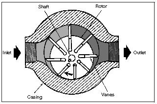
In a vane-type pump, a slotted rotor splined to a drive shaft rotates between closely fitted side plates that are inside of an elliptical- or circular-shaped ring. Polished, hardened vanes slide in and out of the rotor slots and follow the ring contour by centrifugal force. Pumping chambers are formed between succeeding vanes, carrying oil from the inlet to the outlet. A partial vacuum is created at the inlet as the space between vanes increases. The oil is squeezed out at the outlet as the pumping chamber’s size decreases.
Because the normal wear points in a vane pump are the vane tips and a ring’s surface, the vanes and ring are specially hardened and ground. A vane pump is the only design that has automatic wear compensation built in. As wear occurs, the vanes simply slide farther out of the rotor slots and continue to follow a ring’s contour. Thus efficiency remains high throughout the life of the pump.
a. Characteristics. Displacement of a vane-type pump depends on the width of the ring and rotor and the throw of the cam ring. Interchangeable rings are designed so a basic pump converts to several displacements. Balanced design vane pumps all are fixed displacement. An unbalanced design can be built in either a fixed- or variable-displacement pump. Vane pumps have good efficiency and durability if operated in a clean system using the correct oil. They cover the low to medium-high pressure, capacity, and speed ranges. Package size in relation to output is small. A vane pump is generally quiet, but will whine at high speeds.
b. Unbalanced Vane Pumps. In the unbalanced design, (Figure 3-9), a cam ring’s shape is a true circle that is on a different centerline from a rotor’s. Pump displacement depends on how far a rotor and ring are eccentric. The advantage of a true-circle ring is that control can be applied to vary the eccentricity and thus vary the displacement. A disadvantage is that an unbalanced pressure at the outlet is effective against a small area of the rotor’s edge, imposing side loads on the shaft. Thus there is a limit on a pump’s size unless very large hearings and heavy supports are used.
Figure 3-9. Unbalanced vane pump
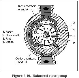
c. Balanced Vane Pumps. In the balanced design (Figure 3-10), a pump has a stationary, elliptical cam ring and two sets of internal ports. A pumping chamber is formed between any two vanes twice in each revolution. The two inlets and outlets are 180 degrees apart. Back pressures against the edges of a rotor cancel each other. Recent design improvements that allow high operating speeds and pressures have made this pump the most universal in the mobile equipment field.
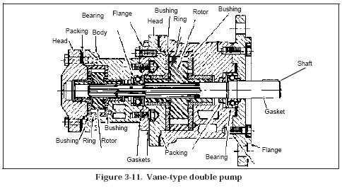
d. Double Pumps. Vane type double pumps (Figure 3- 11) consist of two separate pumping devices. Each is contained in its own respective housing, mounted in tandem, and driven by a common shaft. Each pump also has its own inlet and outlet ports, which may be combined by using manifolds or piping. Design variations are available in which both cartridges are contained within one body. An additional pump is sometimes attached to the head end to supply auxiliary flow requirements.
Double pumps may be used to provide fluid flow for two separate circuits or combined for flow requirements for a single circuit. Combining pump deliveries does not alter the maximum pressure rating of either cartridge. Separate circuits require separate pressure controls to limit maximum pressure in each circuit.
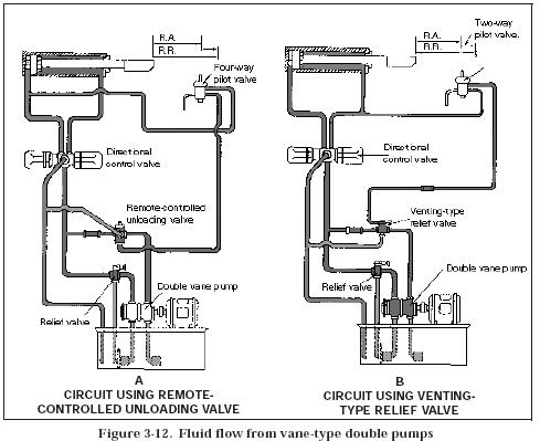
Figure 3-12, shows an installation in which double pumps are used to provide fluid flow for operation of a cylinder in rapid advance and feed. In circuit B, two relief valves are used to control pumping operation. In circuit A, one relief valve and one unloading valve are used to control pumping operations. In both circuits, the deliveries of the pump cartridges are combined after passing through the valves. This combined flow is directed to a four-way valve and to the rest of the circuit.
In circuit B, an upper relief valve is vented when a cylinder rod reaches and trips a pilot valve. A vented relief valve directs the delivery of a shaft end pump cartridge freely back to a tank. Another relief valve controls the maximum pressure of a circuit. An unloading valve and a relief valve in circuit A do the same operation. The output of both pump cartridges combines to supply fluid for a rapid advance portion of a cycle. When the output of one circuit returns to the tank, after reaching a certain point in the cycle, the other circuit completes the advance portion of a cycle. Both pump outputs are then combined for rapid return.
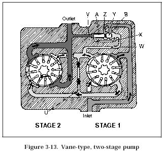
e. Two-Stage Pumps. Two-stage pumps consist of two separate pump assemblies contained in one housing. The pump assemblies are connected so that flow from the outlet of one is directed internally to the inlet of the other. Single inlet and outlet ports are used for system connections. In construction, the pumps consist of separate pumping cartridges driven by a common drive shaft contained in one housing. A dividing valve is used to equalize the pressure load on each stage and correct for minor flow differences from either cartridge.
In operation, developing fluid flow for each cartridge is the same as for single pumps. Figure 3-13 shows fluid flow in a vane-type, two-stage pump. Oil from a reservoir enters a pump’s inlet port and passes to the outlets of the first-stage pump cartridge. (Passages in a pump’s body carry the discharge from this stage to an inlet of the second stage.) Outlet passages in the second stage direct the oil to an outlet port of the pump. Passage U connects both chambers on the inlet side of a second-stage pump and assures equal pressure in both chambers. (Pressures are those that are imposed on a pump from external sources.)
A dividing valve (see Figure 3-13) consists of sliding pistons A and B. Piston A is exposed to outlet pressure through passage V. Piston B is exposed to the pressure between stages through passage W. The pistons respond to maintain a pressure load on a first-stage pump equal to half the outlet pressure at a second-stage pump. If the discharge from the first stage exceeds the volume that can be accepted at the second stage, a pressure rise occurs in passage W. The unbalanced force acting on piston B causes the pistons to move in such a manner that excess oil flows past piston B through passage Y to the inlet chamber of a first-stage cartridge. Fluid throttling across piston B in this manner maintains pressure in passage V.
If the discharge from a first-stage pump is less than the volume required at a second stage pump, a reduced pressure occurs at piston B. An unbalanced force acting on piston A causes the pistons to move so that oil flows past piston A into passages X and W to replenish a second-stage pump and correct the unbalanced condition. Passages Z and Y provide a means for leakage around the pistons to return to the inlet chamber of a first-stage pump. Pistons A and B always seek a position that equally divides the load between the two pumping units.
