Clean the area around the injection pump thoroughly.
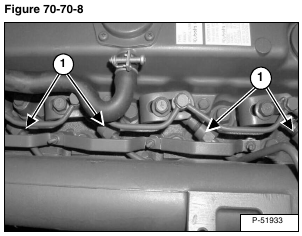
Disconnect the high pressure fuel lines (Item 1) [Figure 70-70-8] from the fuel injectors.
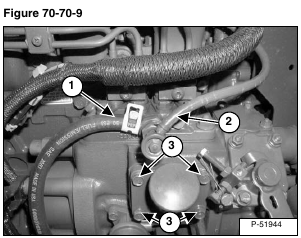
Disconnect the fuel inlet hose (Item 1) and the fuel return hose (Item 2) from the injection pump vent [Figure 70-70-9].
Cap the inlets on the injection pump vent where the hoses were removed [Figure 70-70-9].
Remove the four oil fill tube bolts (Item 3) [Figure 70-70-9].
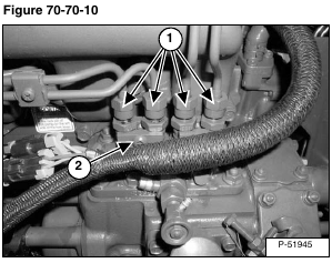
Remove the high pressure fuel lines (Item 1) [Figure 70-70-10] from the injection pump.
Note: Do not loosen the clamp screws (Item 2) [Figure 70-70-10] on the injection pump. This is to be done only when the entire injection pump is sent out to be serviced.
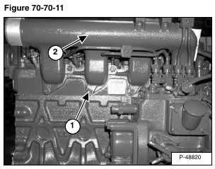
Remove the mounting bolts (Item 1) from the intake manifold (Item 2) [Figure 70-70-11].
Installation: Tighten the mounting bolts to 16 – 20 ft.-lb. (22 – 27 N•m) torque.
Remove the intake manifold from the engine.
Installation: Replace the manifold gasket if it is worn or damaged.
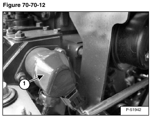
Remove the fuel shutoff solenoid (Item 1) [Figure 70-70-12]. (See Fuel Shutoff Solenoid Removal And Installation on Page 70-70-3.)
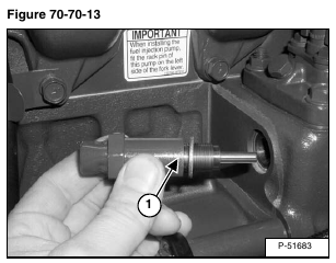
Remove the high-idling body (Item 1) [Figure 70-70-13] from the engine block.
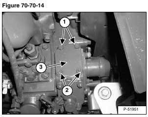
Remove the cover plate bolts (Item 1) and nuts (Item 2) [Figure 70-70-14].
Remove the cover plate (Item 3) [Figure 70-70-14].
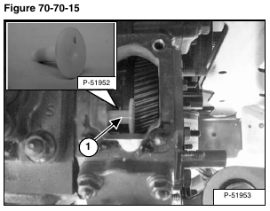
Remove the stop solenoid guide (Item 1) [Figure 70-70-15].
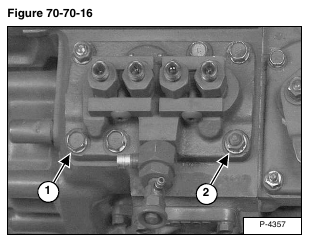
Remove the four mounting bolts (Item 1) and two nuts (Item 2) [Figure 70-70-16] from the injection pump.
Installation: Tighten the mounting bolts to 16 – 20 ft.-lb. (22 – 27 N•m) torque.
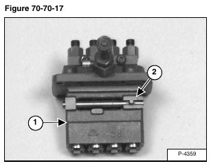
Remove the injection pump (Item 1) [Figure 70-70-17] and shim(s) from the engine.
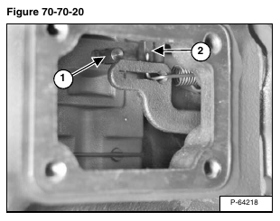
NOTE: The pin (Item 2) [Figure 70-70-17] located on the control rack, needs to be installed correctly during installation. See the following procedure for correct installation.
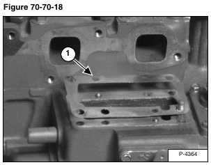
Install the shim(s) (Item 1) [Figure 70-70-18] on the injection pump mounting surface. For information on the number of shims used. (See Injection Pump – Timing on Page 70-70-8.)
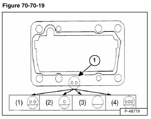
The size of shims are identified by a symbol (Item 1) [Figure 70-70-19] on the shims.
(1) Two holes means 0.0008 in (0.20 mm) shim.
(2) One hole means 0.0010 in (0.25 mm) shim.
(3) Without hole means 0.0012 in (0.30 mm) shim.
(4) Three holes means 0.0014 in (0.35 mm) shim.
Install the injection pump in the engine.
Ensure the control rack pin (Item 1) is to the left side of the fork lever (Item 2) [Figure 70-70-20].
